


Injection Molding Guide 2026: Process, Design, Materials, Cost & Defects
Injection molding is a high-volume manufacturing process that melts plastic resin and injects it into a precision mold cavity. After cooling, the plastic solidifies into a repeatable finished part. This guide explains the complete process, mold design, DFM rules, material selection, cost drivers, common defects, and practical engineering decisions behind successful plastic parts.
What Is Injection Molding? Quick Answer
Injection molding is a manufacturing process that injects molten plastic into a precision mold cavity. The plastic cools, solidifies, and is ejected as a finished part. It is widely used for high-volume plastic products because it provides repeatable dimensions, fast cycle times, complex geometry, and low unit cost after the mold is built.
Injection Molding Process: A Complete Overview
Injection molding is a high-volume manufacturing process in which molten thermoplastic resin is injected under pressure into a precision mold cavity, then cooled and ejected as a finished part. It is widely used across automotive, consumer electronics, medical devices, and packaging industries.
The six stages of injection molding
- Clamping — The two mold halves are closed and locked by the clamping unit before injection begins.
- Injection — Molten resin is injected into the mold cavity at controlled speed and pressure.
- Dwelling (holding) — Holding pressure is maintained to compensate for material shrinkage.
- Cooling — The part solidifies inside the mold; cooling time depends on wall thickness and resin.
- Mold opening — The clamping unit retracts and the mold halves separate.
- Ejection — Ejector pins push the finished part out of the cavity; the cycle repeats.
Injection Molding Topic Hub
This page is designed as the main injection molding guide. Use the links below to go deeper into specific long-tail topics while keeping this page as the central reference for process, design, materials, cost and defects.
Need to verify your part before mold cutting?
Send your 3D file or 2D drawing for a practical DFM review focused on wall thickness, undercuts, gate position, cooling risk and mold cost.
Why This Page Should Be Your Main Injection Molding Guide
This page is not only a beginner explanation of what plastic injection molding is. It is structured as a complete pillar page for engineers, product designers, startups and sourcing teams who need to understand the process before committing to tooling.
Injection molding decisions are connected: material choice affects shrinkage, wall thickness affects sink marks, gate location affects weld lines, cooling affects cycle time, and part geometry affects mold cost. Treating these topics separately often leads to expensive mistakes after mold cutting.
This guide connects those decisions into one practical workflow: define the part requirement, choose a suitable plastic material, design the mold concept, review DFM risks, estimate cost, run mold trials, and solve defects before mass production.
Read the quick answer first, then use the topic hub to jump into the specific problem you are solving: material selection, mold design, DFM, cost, defects or supplier evaluation.
Recommended workflow: start with Part 1 and Part 2 if you are new to injection molding; jump to Part 5, Part 6 and Part 7 if you already have a part design and need practical engineering decisions.
Fundamentals — Understanding Injection Molding
1.1 What Is Injection Molding?
Injection Molding (IM) is a mass-production process in which molten material is injected under high pressure into a pre-designed plastic mold cavity, cooled and solidified to obtain a finished product. For a visual walk-through of how injection molding works, see our supplementary explainer.
Imagine making a waffle. You pour batter (molten plastic) into the waffle iron’s grid pattern (mold cavity), close the lid (clamping), wait for it to cook (cooling & solidification), then open and remove the finished waffle (ejection).
The core principle of injection molding is exactly the same — except the “batter” is molten plastic at 200 – 400 °C, the “pouring” is high-pressure injection at 500 – 2,000 bar, and the “waffle iron” is a precision steel mold worth tens of thousands to millions of dollars with micron-level accuracy.
Core Characteristics of Injection Molding
| Characteristic | Description |
|---|---|
| High Efficiency | A single molding cycle typically lasts 10 – 60 seconds; daily output can reach tens of thousands of parts |
| High Precision | Dimensional tolerances can be held to ±0.05 mm or better |
| High Consistency | Part #1 and part #100,000 are virtually identical |
| Complex Geometry | Extremely complex 3D shapes can be formed in a single cycle |
| Material Diversity | Thousands of thermoplastic and thermoset materials are available |
| Low Per-Unit Cost | The larger the batch, the lower the unit cost (strong economies of scale) |
Typical Application Areas
| Industry | Typical Product Examples |
|---|---|
| Consumer Electronics | Phone cases, charger housings, earphone shells, remote controls — see injection molding in electronics |
| Automotive | Dashboards, bumpers, headlight lenses, interior trim panels — learn more about IM in the automotive industry |
| Medical Devices | Syringes, blood collection tubes, inhaler components — explore medical injection molding 101 |
| Packaging | Bottle caps, food containers, cosmetic bottles |
| Household Products | Storage bins, hangers, toothbrushes, toys |
| Agriculture | Planters, irrigation fittings, livestock equipment — discover why IM dominates agriculture |
| Industrial Equipment | Gears, bearing cages, pipe fittings, electrical enclosures |
1.2 A Brief History of Injection Molding: From Celluloid to Smart Factories
Understanding the history of mold design helps you grasp the evolutionary logic and future direction of this process.
Every major leap in injection molding has occurred at the intersection of material innovation, machine technology, and digital tools. This pattern continues to this day — see the key trends reshaping the industry.
1.3 Injection Molding vs. Other Manufacturing Processes: When to Choose IM?
Injection molding is not a silver bullet. Selecting the right manufacturing process is the first step to project success. For a focused comparison, read our injection molding vs. 3D printing deep dive, or the broader 3D printing vs. CNC vs. vacuum casting comparison.
Process Comparison Decision Matrix
| Dimension | Injection Molding | 3D Printing (FDM/SLA) | CNC Machining | Blow Molding | Compression Molding |
|---|---|---|---|---|---|
| Ideal Volume | 1,000 – millions | 1 – 500 | 1 – 5,000 | 1,000 – millions | 1,000 – 50,000 |
| Unit Cost (high vol.) | ⭐ Very low | ✗ High | Medium | ⭐ Very low | Low |
| Tooling Cost | ✗ High ($3K – $100K+) | ⭐ None | ⭐ None | High | Medium |
| Geometric Complexity | ⭐ Very high | ⭐ Very high | Medium | Low (hollow only) | Low – Medium |
| Dimensional Accuracy | ⭐ Very high | Medium | ⭐ Very high | Medium | Medium |
| Surface Quality | ⭐ Excellent | Requires post-processing | ⭐ Excellent | Good | Good |
| Material Options | ⭐ Extremely broad | Limited | ⭐ Extremely broad | Limited | Limited (thermosets) |
| Production Speed | ⭐ Very fast | ✗ Slow | Medium | Fast | Medium |
| Lead Time | 4 – 12 weeks (incl. tooling) | 1 – 5 days | 1 – 10 days | 6 – 16 weeks | 4 – 10 weeks |
When to Choose Injection Molding — Decision Principles
✅ Suitable for IM when:
- Expected total volume > 1,000 parts
- High consistency, high-precision dimensions & surface finish are required
- Product design is essentially frozen (mold modifications are costly)
- Specific material properties are needed (chemical resistance, food-grade, flame retardant)
- Lowest possible per-unit cost is the goal
❌ Not suitable for IM when:
- Volume is extremely low (< 500 parts) and budget is limited — consider low-volume injection molding instead
- Design is still in rapid iteration
- Product is extremely large (e.g., > 1 m, exceeding standard clamp force)
- All-metal parts are required (use CNC, casting, or powder metallurgy)
See: Part 6 — Cost Analysis & Optimization to learn how to calculate whether your project reaches the break-even point for injection molding. You can also try our smart injection mold cost calculator.
Process Deep Dive
2.1 The Complete Injection Molding Process (Six Steps)
Every molding cycle can be broken down into six key stages. Understanding the physics and controllable parameters of each stage is the foundation for optimizing product quality. For a detailed visual walk-through, see the injection molding process from concept to production.

Clamping
The two mold halves (moving & fixed) close and lock under the clamping mechanism. Clamp force must exceed the melt’s expansion force on the cavity walls, or flash occurs.
Injection
Pre-plasticized molten plastic is pushed into the mold cavity at high speed & pressure by the screw (acting as a plunger). Typical injection pressure: 500 – 1,500 bar.
Packing / Holding
After the cavity is essentially filled, the screw maintains a lower but sustained pressure to compensate for volumetric shrinkage (1% – 3%) during cooling.
Cooling
The melt dissipates heat through cooling channels in the mold and gradually solidifies. Cooling typically accounts for 60% – 80% of the total cycle time.
Ejection
The mold opens and the part is pushed out by the ejection system — ejector pins, stripper plates, air valves, or robotic arms.
Cycle Repeat
After part removal (often automated by robot), the mold closes again and the next cycle begins. Estimate your throughput with our cycle time calculator.
Molten plastic doesn’t fill the cavity like pouring water into a glass. Instead, it advances from the gate with a “fountain flow” pattern — like an expanding balloon. Understanding this flow behavior is fundamental to solving defects. See: Part 7 — 7.1 Defect Troubleshooting
Packing is like inflating a balloon to the right size, then pinching the opening shut while adding a tiny bit more air to keep it plump. Without packing, sink marks appear on your part surfaces.
Typical Cycle Times
| Product Type | Typical Wall Thickness | Typical Cycle Time |
|---|---|---|
| Thin-wall packaging (yogurt cups) | 0.4 – 0.8 mm | 3 – 6 sec |
| Consumer electronics housings | 1.2 – 2.0 mm | 15 – 30 sec |
| Automotive interior parts | 2.0 – 3.5 mm | 30 – 60 sec |
| Thick-wall industrial parts | 4.0 – 6.0 mm | 60 – 120+ sec |
2.2 Core Components of an Injection Molding Machine
An injection molding machine consists of two main units. For a deeper look at mold structure, see our dedicated article.

Injection Unit — Key Components
| Component | Function | Key Parameters |
|---|---|---|
| Hopper | Stores and feeds raw material pellets | Capacity; integrated drying capability |
| Barrel | Metal cylinder enclosing the screw, wrapped with heater bands | Temperature zone control (typically 3 – 5 zones) |
| Screw | Core component — rotates to convey, compress, shear-heat, and mix plastic | Diameter (D); L/D ratio (18:1 – 24:1); compression ratio |
| Check Ring (Non-Return Valve) | Prevents melt backflow during injection | Wear leads to inaccurate metering |
| Nozzle | Connection channel between barrel and mold | Orifice diameter; temperature control |
Machine Classification
| Classification | Type | Characteristics |
|---|---|---|
| By Drive | Hydraulic | Low cost, high clamp force, but lower precision and energy efficiency |
| All-Electric | High precision, high energy efficiency, clean & quiet; ideal for medical/electronics | |
| Hybrid | Combines hydraulic power with electric precision | |
| By Clamp Force | Micro (< 30 tons) | Micro connectors, medical micro-parts — see micro injection molding |
| Medium (30 – 500 tons) | Most common; covers the majority of consumer products | |
| Large (500 – 6,000+ tons) | Automotive bumpers, large containers |
2.3 Key Process Parameters Explained
Mastering the meaning and adjustment logic of these parameters is the key to stable mass production. For even more granular process tips, see our supplementary article.
| Parameter | Definition | Typical Range | Consequence of Incorrect Setting |
|---|---|---|---|
| Barrel Temperature | Temperature settings for each heating zone | 180 – 350 °C (material-dependent) | Too high: material degradation; Too low: incomplete plasticization |
| Mold Temperature | Temperature maintained via cooling/heating system | 20 – 120 °C | Too high: long cycles; Too low: poor surface quality |
| Injection Speed | Screw forward speed | 10 – 500 mm/s | Too fast: jetting, gas traps; Too slow: short shots, flow marks |
| Injection Pressure | Maximum pressure during injection | 500 – 2,000 bar | Too high: flash, internal stress; Too low: short shots |
| Packing Pressure | Pressure applied during packing | 40% – 80% of injection pressure | Too high: overpacking, flash; Too low: sink marks |
| Packing Time | Duration of packing | 2 – 15 sec | Too short: sink marks; Too long: wasted cycle time |
| Cooling Time | Time for part solidification in cavity | 5 – 60+ sec | Too short: warpage; Too long: wasted efficiency |
| Back Pressure | Resistance against screw retraction during plasticization | 3 – 15 bar | Too low: uneven mixing; Too high: shear overheating |
When adjusting injection molding process parameters, always follow the “change only one variable at a time” principle. Adjusting multiple parameters simultaneously makes it impossible to isolate the root cause — exactly like the “controlled experiment” method in science.
Material Science — Choose the Right Material, Win Half the Battle
3.1 Thermoplastics vs. Thermosets
Materials used in injection molding fall into two major camps. If you’re new to identifying plastic materials, start with our primer.
| Property | Thermoplastics | Thermosets |
|---|---|---|
| Heating Behavior | Can be repeatedly heated to soften and cooled to solidify | Undergoes irreversible chemical cross-linking when heated |
| Analogy | Like chocolate — can be melted and reshaped | Like a boiled egg — once cooked, cannot return to raw |
| Recyclability | ✅ Recyclable for re-pelletizing | ❌ Cannot be re-melted |
| IM Market Share | ~90% | ~10% |
| Typical Examples | PP, ABS, PA, PC, POM | Phenolic resin, Epoxy, Silicone |
| Typical Applications | Consumer goods, automotive, electronics | Electrical insulation, brake pads, high-temp components |
Unless your application has explicit high-temperature or electrical insulation requirements, prioritize thermoplastics — wider selection, more mature supply chains, and less environmental pressure. Learn more about the advantages and disadvantages of plastics.
3.2 Top 10 Injection Molding Materials — Detailed Guide
Commodity Plastics Low Cost & Highest Volume
Engineering Plastics Better Performance, Moderate Cost
High-Performance Plastics Special Needs, Higher Cost
3.3 Material Selection Decision Framework
Facing thousands of material grades, how do you systematically choose? Use this five-step filtering method:
Material selection is not “just use whatever the supplier recommends.” With this framework, you can lead material discussions like an expert.
See: Part 5 — Design for Manufacturing (DFM) — Material selection and product design are tightly coupled; certain materials have specific requirements for wall thickness and draft angles.
Mold Design & Engineering
The mold is the core asset of injection molding — and the component with the largest investment and longest lead time. A well-made mold can produce millions of qualified parts; a flawed mold will trap you in an endless cycle of modifications, downtime, and quality disputes. For a broader look at mold design fundamentals, see our dedicated guide.
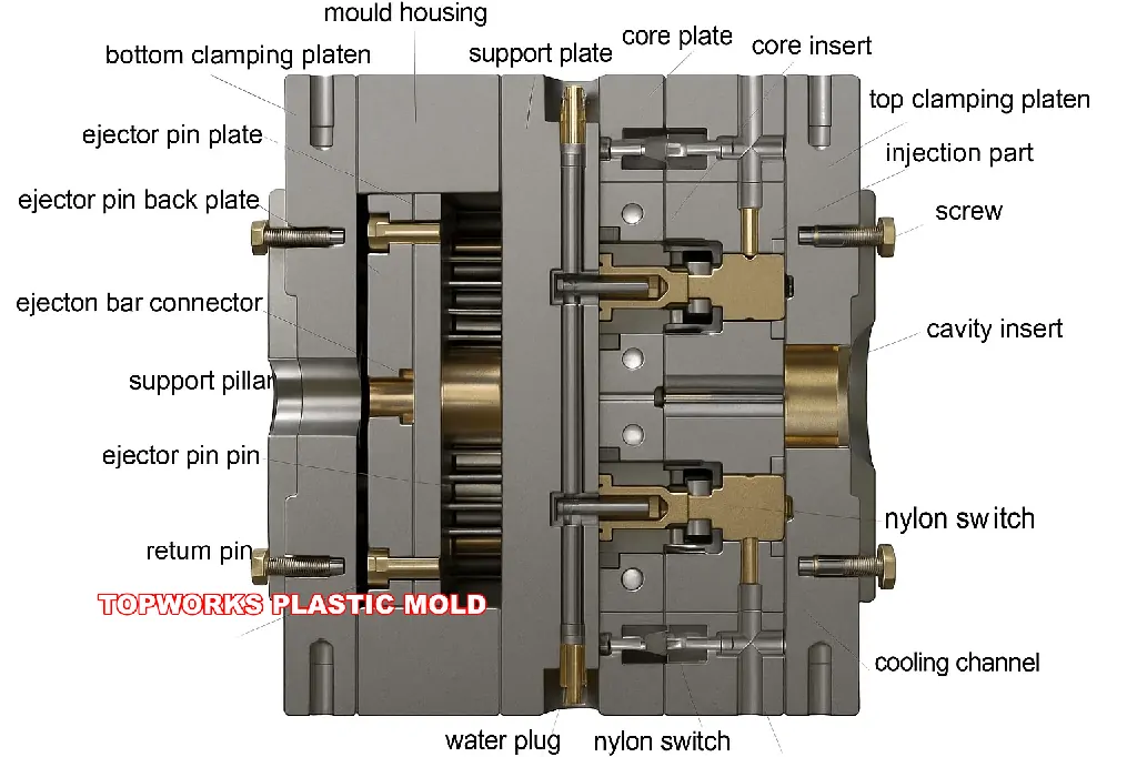
4.1 Mold Structure Anatomy
A standard two-plate mold consists of the following core components:
Cavity vs. Core
| Concept | Description |
|---|---|
| Cavity | The mold portion that forms the outer surface of the product (typically on the fixed half) |
| Core | The mold portion that forms the inner surface of the product (typically on the moving half) |
| Design Principle | As the part cools, it shrinks and “grips” the core — so the part typically stays on the moving half for easy ejection by ejector pins |
Multi-Cavity Molds
A single mold can contain multiple identical cavities (multi-cavity mold), producing multiple parts per cycle. You can also use a family mold if you need different parts in the same cycle.
| Cavities | Suitable Scenario | Cost Impact |
|---|---|---|
| 1 cavity | Prototyping, low volume, large parts | Lowest mold cost |
| 2 – 4 cavities | Medium volume | Mold cost increases 50% – 200% |
| 8 – 16 cavities | High volume consumer products | High mold cost, but very low per-unit mold amortization |
| 32 – 128 cavities | Bottle caps, disposable medical consumables — ultra-high volume | Mold cost $100K – $1M+, but per-unit cost is minimal |
Cavity count is determined by: Annual volume requirement ÷ Available production days ÷ Daily output target. Doubling cavities ≠ doubling cost, but mold precision and maintenance complexity increase exponentially. Understand how costs scale with production volume.
4.2 Runner & Gate System Design
The runner system is the delivery channel network from the machine nozzle to the cavity.

Cold Runner vs. Hot Runner
| Comparison | Cold Runner | Hot Runner |
|---|---|---|
| Principle | Melt in the runner solidifies each cycle | Melt in the runner is kept molten by electric heaters |
| Waste | Runner waste every cycle (must be regrind or discarded) | ⭐ Zero runner waste |
| Mold Cost | ⭐ Low | High (hot runner system alone costs $5K – $50K+) |
| Cycle Time | Longer (runner needs cooling) | ⭐ Shorter |
| Best For | Low volume, simple parts, limited budget | High volume, multi-cavity, expensive materials |
| Maintenance | ⭐ Simple | More complex (heaters, controllers, flow balancing) |
Gate Types
The gate is the narrowest passage connecting the runner to the cavity. Its location and type directly affect fill pattern, appearance, and strength.
| Gate Type | Characteristics | Typical Application |
|---|---|---|
| Edge Gate | Most common; located on the parting line; requires manual or automatic gate removal | General-purpose parts |
| Submarine / Tunnel Gate | Gate below parting line; auto-shears on mold opening — no post-processing | Cosmetic parts |
| Pin Gate | Extremely small gate; minimal vestige; used with three-plate molds or hot runners | Cosmetic parts, multi-cavity |
| Fan Gate | Wide and thin; provides a uniform melt front | Flat panel-shaped parts |
| Valve Gate | Hot runner only; mechanical needle valve controls flow — gate vestige nearly invisible | High-end cosmetic parts (auto, electronics) |
The gate should be located at the thickest wall section, allowing melt to flow from thick to thin. This ensures optimal packing effectiveness and minimizes sink marks. See: 5.1 Wall Thickness Design. Also explore how wall thickness & gate choice affect mold cost.
4.3 Cooling System & Ejection Mechanisms
Cooling System
The cooling system‘s goal is to uniformly and rapidly remove heat from the cavity.
Conventional Cooling: Straight-line water channels drilled into the mold (gun-drilled holes) with circulating coolant.
Limitation: Straight channels cannot perfectly conform to complex cavity surfaces, causing some areas to cool faster than others — resulting in warpage.
Advanced Technology — Conformal Cooling
- Uses 3D metal printing (DMLS/SLM) to manufacture mold inserts with cooling channels that follow the cavity contours
- Cooling uniformity improves 40% – 70%; cycle time reduction of 20% – 40%
- Higher cost, but ROI is excellent for high-volume molds
Ejection Mechanisms
| Mechanism Type | Purpose | Considerations |
|---|---|---|
| Ejector Pins | Most common; cylindrical metal pins push the part out | Leaves circular pin marks on the part surface — place on non-cosmetic surfaces |
| Stripper Plate | An annular plate pushes the entire part out uniformly | Suitable for thin-wall, deep-draw parts; even ejection force |
| Slides | Mold blocks that move perpendicular to the mold open direction — for external undercuts | Increases mold complexity and cost |
| Lifters | Move at an angle during mold opening — for internal undercuts | More compact than slides, but limited stroke |
| Air Poppet Valves | Compressed air pushes the part out | Suitable for thin-wall, deep cup-shaped parts |
4.4 Mold Steel Selection & Lifespan
Choosing the right mold steel is critical for balancing tooling cost against production life.
| Mold Class (SPI/SPE) | Expected Lifespan | Typical Steel | Cost Level | Suitable Scenario |
|---|---|---|---|---|
| Class 101 | > 1,000,000 cycles | S136 (stainless), H13 | $$$$$ | Ultra-high volume, 24/7 production |
| Class 102 | < 1,000,000 cycles | P20 hardened, H13 | $$$$ | High volume, high quality demands |
| Class 103 | < 500,000 cycles | P20 (pre-hardened steel) | $$$ | Medium volume — most commonly used class |
| Class 104 | < 100,000 cycles | P20, Aluminum alloy | $$ | Low volume production |
| Class 105 | < 500 cycles | Aluminum, Epoxy, 3D-printed | $ | Prototyping & functional testing |
Don’t blindly pursue the highest mold steel grade. First, clearly define your total volume expectation, then match the mold class accordingly — this can save 30% – 60% of your mold investment. Also plan for long-term mold maintenance and proper storage to protect your investment.
Design for Manufacturing (DFM)
Before you finalize the 3D design, check these DFM risks.
Small changes to wall thickness, ribs, bosses, side holes and draft can prevent sink marks, warpage, sliders, extra mold cost and delayed production.
“A good product is not designed first and then adapted to the process — it is co-evolved with the process from the very beginning of design.” Read our in-depth guide on DFM in injection molding.
DFM’s core philosophy: systematically consider the constraints and capabilities of the injection molding process during the product design stage, eliminating design features that could lead to defects, high costs, or un-manufacturability at the source. For the foundational design principles for plastic parts, see our companion article.
5.1 Wall Thickness Design — The #1 Rule of IM DFM
Wall thickness is the single most critical design parameter affecting quality, cost, and cycle time of injection molded products — bar none. Use our wall thickness calculator to quickly validate your design.
Fundamental Principles
| Principle | Description |
|---|---|
| ⭐⭐⭐⭐⭐ Uniform Wall Thickness | The most important principle. Uneven walls cause differential shrinkage → sink marks, warpage, internal stress |
| Gradual Wall Transitions | If thickness changes are unavoidable, use gradual transitions (transition length ≥ 3× the thickness difference), never abrupt changes |
| Avoid Excess Thickness | Thicker walls → longer cooling → longer cycles → higher cost → greater sink mark risk. See thick-wall molding challenges |
| Avoid Excess Thinness | Thinner walls → higher injection pressure/speed needed → faster mold wear → risk of short shots |
Recommended Wall Thickness by Material
| Material | Recommended Range | Optimal (Performance & Cost Balance) |
|---|---|---|
| PP | 0.8 – 3.8 mm | 1.5 – 2.5 mm |
| PE | 0.8 – 3.0 mm | 1.5 – 2.5 mm |
| ABS | 1.0 – 3.5 mm | 1.5 – 2.5 mm |
| PC | 1.0 – 4.0 mm | 1.8 – 3.0 mm |
| PA (Nylon) | 0.8 – 3.0 mm | 1.2 – 2.0 mm |
| POM | 0.8 – 3.0 mm | 1.5 – 2.5 mm |
Wall thickness uniformity is like baking a cake — if the cake thickness is uneven, the thin parts are already burnt while the thick parts are still raw inside. The same applies to injection molding: uneven walls mean thin sections have solidified while thick sections are still molten, causing differential shrinkage that leads to sink marks and warpage.
5.2 Draft Angles, Fillets & Ribs
Draft Angle
A draft angle is a slight taper applied to product surfaces relative to the mold opening direction, ensuring the part can be smoothly ejected from the mold. For parts with undercuts, special slide or lifter mechanisms are needed.
| Surface Type | Recommended Draft Angle |
|---|---|
| Smooth, untextured surface | ≥ 0.5° (recommended 1° – 2°) |
| Light texture (e.g., SPI B-2) | ≥ 1.5° |
| Deep texture / leather grain (e.g., MT-11010) | ≥ 3° – 5° |
| Deep cavity / tall ribs | Add 1° for every 25 mm of depth |
The deeper the texture, the larger the draft angle. General rule: 1° of additional draft for every 0.025 mm of texture depth. Understanding this relationship also affects mold surface finish choices.
Fillets (Radii)
All internal and external corners should have fillet radii — avoid sharp right angles.
| Location | Recommended Value |
|---|---|
| Internal fillet radius | ≥ 50% of wall thickness (ideal: 75%) |
| External fillet radius | Internal radius + wall thickness |
Why?
- Sharp corners are stress concentration points — parts are most likely to crack here
- Sharp corners impede melt flow — prone to short shots and weld lines
- Sharp corners increase mold manufacturing difficulty — EDM machining of sharp corners is expensive and prone to damage
Ribs
When wall thickness alone doesn’t provide sufficient rigidity, don’t increase the wall thickness (costly, more sink marks) — add ribs instead.
| Rib Design Rule | Recommended Value | Reason |
|---|---|---|
| Rib thickness | ≤ 50% – 70% of wall thickness | Ribs too thick create thick sections at the base → sink marks |
| Rib height | ≤ 3× wall thickness | Excessively tall ribs are hard to fill and eject |
| Base fillet | 0.25 – 0.5 × wall thickness | Eliminates stress concentration |
| Rib draft angle | ≥ 0.5° per side | Ensures smooth ejection |
| Rib spacing | ≥ 2× wall thickness | Spacing too close → mold-side cooling difficulty, hot spots |
5.3 Snap Fits, Threads & Insert Molding
Snap Fits
Snap fits are the most commonly used fastener-free assembly method for injection molded parts — saving screw costs and simplifying assembly.
- Maximum allowable deflection strain of a cantilever snap depends on the material (ABS ≈ 2 – 5%, PP ≈ 5 – 8%, PC ≈ 1 – 2%)
- The cantilever root needs generous fillet transitions (R ≥ 0.5 × wall thickness)
- For repeated assembly/disassembly, design a lead-in ramp angle of 30° – 45°
Threads
- External threads can be directly injection molded (require splitting on the parting line, or unscrewing mechanisms)
- Internal threads typically use unscrewing cores or metal threaded inserts
- For frequently tightened applications (> 10 cycles), use metal threaded inserts (heat-staked or ultrasonically installed) instead of molded plastic threads
Insert Molding
Metal components (nuts, pins, bearings) are pre-placed into the mold before plastic is injected around them. Our guide to insert molding covers the full process, and you can compare it with other approaches in overmolding vs. insert molding.
- Advantage: One-step metal-plastic composite part; high bond strength
- Caution: The thermal expansion coefficient difference between metal and plastic is large. The plastic wall surrounding the insert must be thick enough (typically ≥ 50% of insert diameter), otherwise radial cracks form during cooling.
5.4 DFM Checklist
Before sending design files to your mold supplier, review against this checklist item by item. For even more nuance, explore the 7 crucial DFM questions and DFM & FMEA risk reduction.
- Wall thickness uniformity check — variation ≤ ±15% (ideal ≤ ±10%)
- Minimum wall thickness satisfies material requirements
- All wall thickness transitions are gradual (transition length ≥ 3× thickness difference)
- All internal corners have fillets R ≥ 0.5× wall thickness
- All external surfaces have adequate draft angle (≥ 1° smooth; increase per texture depth)
- Rib thickness ≤ 60% of wall thickness; height ≤ 3× wall thickness
- Boss OD ≤ 2.5× wall thickness; boss wall ≤ 60% of nominal wall
- Undercuts are identified & evaluated (slides/lifters needed? Can they be designed out?)
- Gate location recommendations are annotated (non-cosmetic, non-functional areas)
- Parting line location confirmed (no impact on appearance or assembly)
- Ejector pin locations confirmed (non-cosmetic surfaces only)
- Material finalized; Material Technical Data Sheet (TDS) obtained
- Shrinkage rate incorporated into dimensional tolerance calculations
- Moldflow analysis completed to verify fill, pack, and cooling
Cost Analysis & Optimization
6.1 The Four Components of Injection Molding Cost
Injection Molding Cost Calculator
This calculator estimates the cost of plastic injection molding based on material, volume, and cycle time…
For a comprehensive primer, see our companion guide to mastering injection molding costs.

Typical Cost Breakdown (Medium-Volume Consumer Product)
| Cost Component | Approximate Share |
|---|---|
| Mold Amortization | 15% – 30% (decreases with higher volume) |
| Raw Material | 30% – 50% |
| Processing (Machine Time + Labor) | 20% – 35% |
| Post-Processing | 5% – 15% |
6.2 Mold Cost Estimation
Use our interactive mold cost calculator for a quick estimate, or read the detailed guide on how much a plastic mold costs.
| Factor | Impact on Cost |
|---|---|
| Product Size | Larger part → larger mold → more steel & machining cost |
| Geometric Complexity | Undercuts, deep cavities, precision textures → slides, lifters, EDM → cost rises. Read why injection mold prices vary widely |
| Number of Cavities | More cavities → larger & more complex mold → but lower per-unit mold amortization |
| Mold Steel | P20 pre-hardened << S136 stainless < H13 hot-work steel |
| Precision Requirements | ±0.1 mm (standard) << ±0.02 mm (high-precision optical grade) |
| Hot Runner System | Cold runner: no extra cost; Hot runner: adds $5K – $50K |
| Manufacturing Region | China ≈ $3K – $50K; US/Europe ≈ $10K – $200K (same-spec mold) |
Rough Estimation Reference
| Product Complexity | Single-Cavity Mold Price (China) | Single-Cavity Mold Price (US/EU) |
|---|---|---|
| Simple (no undercuts, smooth) | $2,000 – $8,000 | $8,000 – $30,000 |
| Medium (1 – 2 slides, simple texture) | $8,000 – $25,000 | $25,000 – $75,000 |
| Complex (multi-slide, hot runner, fine texture) | $25,000 – $80,000 | $75,000 – $250,000+ |
If you’re considering sourcing from China, learn how to compare injection molding quotes and watch for hidden costs in Chinese injection moulding.
6.3 Seven Strategies to Reduce Per-Unit Cost
For an additional checklist, see our article on 7 tips to reduce injection molding costs and the 5-step framework to cut China sourcing costs by 20%.
| Strategy | Principle | Expected Savings |
|---|---|---|
| ① Optimize Wall Thickness (Thinner) | Less material + shorter cooling = dual savings on material & machine time | 10% – 25% |
| ② Use Ribs Instead of Thick Walls | Achieve rigidity through ribs, not added wall thickness | 5% – 15% |
| ③ Increase Cavity Count | More parts per cycle → spread machine time cost | 20% – 50% (high vol.) |
| ④ Use Hot Runner | Eliminate runner waste — especially impactful for expensive materials | 5% – 20% |
| ⑤ Material Substitution | Switch to a lower-cost material that still meets performance requirements | 10% – 40% |
| ⑥ Automate Post-Processing | Robotic part removal, auto-degating, auto-inspection → reduce labor. See automation & robotics for IM | 15% – 30% (post-proc.) |
| ⑦ Design Integration (Part Consolidation) | Merge multiple parts into one molded piece → eliminate assembly steps & fasteners | 20% – 50% (system-level) |
Strategy ⑦ (design integration) is epitomized by Tesla’s single-piece die-cast rear underbody — consolidating 70+ stamped and welded parts into a single giant aluminum casting, eliminating 300 welding robots and reducing production costs by 40%. Although that’s die casting rather than injection molding, the cost-reduction logic of “consolidate parts” is identical. Explore automotive lightweighting through advanced IM techniques for similar strategies.
See: 5.1 Wall Thickness Design to learn how to safely reduce wall thickness without sacrificing performance.
Defect Troubleshooting & Quality Control
7.1 Twelve Most Common Injection Molding Defects
Mastering defect identification and troubleshooting is the dividing line between an “ordinary operator” and an “injection molding engineer.” For a complementary overview, read our analysis of injection molding defects and their resolution.
The following twelve defects are ranked by frequency of occurrence:
Appearance: Localized depressions on the product surface, typically on the back side of ribs, bosses, or thick-wall areas.
Root Cause: Thick-wall areas cool slowly; internal material continues to shrink and pulls the already-solidified outer surface inward. See our dedicated sink mark solutions guide.
| Troubleshooting Level | Corrective Action |
|---|---|
| Design | Reduce rib thickness (≤ 60% of wall); avoid abrupt thickness changes; consider gas-assist IM |
| Process | Increase packing pressure; extend packing time; lower mold temperature |
| Mold | Optimize gate location (closer to thick sections); enlarge gate size |
Appearance: Thin flaps of excess material at parting lines or ejector pin holes. See a real-world flash defect case study.
Root Cause: Insufficient clamp force or damaged parting surfaces allow melt to seep into gaps.
| Troubleshooting Level | Corrective Action |
|---|---|
| Machine | Increase clamp force |
| Mold | Repair parting surfaces (re-grind, polish); check for mold deformation |
| Process | Reduce injection pressure/speed; lower melt temperature |
Appearance: Part not completely filled; missing material at the flow end.
Root Cause: The melt front freezes before reaching the end of the cavity.
| Troubleshooting Level | Corrective Action |
|---|---|
| Process | Increase injection speed/pressure; increase melt/mold temperatures |
| Mold | Add/clean vents (critical!); enlarge gate/runner size |
| Design | Increase wall thickness in thin areas; optimize gate position |
Appearance: Fine line-shaped marks where two melt fronts meet.
Root Cause: Two melt fronts have cooled too much by the time they converge, preventing full fusion.
| Troubleshooting Level | Corrective Action |
|---|---|
| Process | Increase melt and mold temperatures; increase injection speed |
| Mold | Relocate gates (move weld lines to non-critical areas); improve venting |
| Design | If through-holes exist, consider changing to blind holes (avoid melt splitting around them) |
Weld lines cannot be completely eliminated (they form whenever melt splits and reconverges) — they can only be relocated or minimized.
Appearance: Part bends, twists, or bows after ejection; fails flatness/straightness requirements. See our deformation case studies for real-world examples.
Root Cause: Different areas of the part cool at different rates → uneven shrinkage → internal stress release causes deformation.
| Troubleshooting Level | Corrective Action |
|---|---|
| Design | Uniform wall thickness (the most fundamental fix); add ribs for rigidity |
| Mold | Optimize cooling channels for uniformity; consider conformal cooling |
| Process | Extend cooling time; minimize temperature difference between core/cavity sides (≤ 10 °C) |
| Material | Switch to material with lower or more isotropic shrinkage |
Appearance: Black or brown scorch spots at flow ends or dead corners of the cavity.
Root Cause: Trapped air is compressed adiabatically by the advancing melt (like a diesel engine’s ignition), reaching temperatures of hundreds of degrees and charring the plastic.
| Troubleshooting Level | Corrective Action |
|---|---|
| Mold | Add or clean vents (most critical!) — vent depth typically 0.02 – 0.05 mm. See why venting is so important |
| Process | Reduce injection speed (especially in the final stage); reduce clamp force slightly (allow micro-leakage of air through the parting line) |
Appearance: Ring-shaped or wave-like patterns on the surface, typically radiating outward from the gate.
Root Cause: Insufficient melt front temperature or uneven flow speed prevents the surface layer from spreading smoothly.
| Troubleshooting Level | Corrective Action |
|---|---|
| Process | Increase injection speed; increase melt/mold temperatures |
| Mold | Enlarge gate size; optimize gate position |
Appearance: Silvery-white streaks on the surface along the flow direction.
Root Cause: Moisture in the material (excessive water content), volatile gases, or trapped air stretched into thin layers during melt flow.
| Troubleshooting Level | Corrective Action |
|---|---|
| Material | Thoroughly dry the resin — PC: 120 °C/4 h; PA: 80 °C/8 – 12 h |
| Process | Lower back pressure (reduce air entrapment); reduce screw RPM |
Appearance: A snake-like, folded pattern extending from the gate.
Root Cause: Melt shoots out of a narrow gate at excessive speed into an open cavity — like a thin water jet spraying into a large pool, never forming a stable fountain-flow front.
| Troubleshooting Level | Corrective Action |
|---|---|
| Process | Reduce initial injection speed (multi-stage speed: slow start → fast middle) |
| Mold | Enlarge gate size; aim the gate at a wall (let melt impinge and spread) |
Appearance: Hollow spaces inside the part (visible on cross-section). See our bubbles troubleshooting guide for more detail.
Root Cause: In thick sections, the outer layer solidifies first while the internal melt continues to shrink without backfill → vacuum voids form; or moisture/gas in material creates bubbles.
| Troubleshooting Level | Corrective Action |
|---|---|
| Design | Reduce wall thickness; eliminate thick sections |
| Process | Increase packing (for vacuum voids); thoroughly dry material (for bubbles) |
Appearance: White marks at ejector pin locations or snap-fit areas. See our stress mark solutions.
Root Cause: Part has not sufficiently cooled and solidified at the time of ejection; ejection force causes localized material yielding.
| Troubleshooting Level | Corrective Action |
|---|---|
| Process | Extend cooling time; reduce ejection speed |
| Mold | Add more ejector pins (distribute force); increase draft angles |
Appearance: Uneven coloration on the product or batch-to-batch color differences.
Root Cause: Uneven mixing of color masterbatch, insufficient screw mixing capability, or batch-to-batch pigment variation from the color masterbatch supplier.
| Troubleshooting Level | Corrective Action |
|---|---|
| Material | Use pre-colored pellets instead of masterbatch blending; verify supplier batch consistency |
| Process | Increase back pressure and screw RPM (improve mixing); increase metering stroke |
7.2 Systematic Troubleshooting Methodology
When defects appear, don’t randomly adjust parameters by intuition. Use this four-layer approach. For extra guidance, browse our product defect troubleshooting reference.
During initial mold trial (T1), once you produce parts that meet all quality criteria, immediately freeze and record all process parameters (barrel temps, injection speed/pressure profile, packing parameters, cooling time, etc.) and keep physical “golden samples” for future comparison. When defects emerge later, comparing current parts to golden samples and current parameters to recorded settings quickly narrows down the root cause.
7.3 Quality Control Framework
A robust QC framework ensures consistent output over millions of cycles. Pair this with our quality control in injection molding deep dive.
Incoming Quality Control (IQC)
- Verify resin lot number, moisture content (moisture analyzer), and melt flow index (MFI)
- Cross-reference Certificate of Analysis (CoA) with material TDS specifications
- Inspect colorant / masterbatch consistency (color chip comparison under D65 light)
In-Process Quality Control (IPQC)
- First Article Inspection (FAI): Measure the first 3 – 5 shots against the drawing after every startup, mold change, or parameter change
- SPC Monitoring: Track critical dimensions with Statistical Process Control charts (X̄-R or X̄-S); react when Cpk drops below 1.33
- Visual Inspection: Operators check every N-th part (or 100% for medical/safety-critical) against a limit sample set (good / marginal / reject)
- Process Monitoring: Modern machines log cavity pressure, cushion position, and cycle time — flag any out-of-window shots automatically
Outgoing Quality Control (OQC)
- AQL sampling inspection per ISO 2859-1 (typical AQL levels: Critical = 0, Major = 1.0, Minor = 2.5)
- Functional testing (e.g., snap-fit engagement force, seal leak test, drop test)
- Full dimensional report (CMM or structured-light scanner) on a defined frequency
| QC Tool | What It Measures | When to Use |
|---|---|---|
| Calipers / Micrometers | Linear dimensions ± 0.01 mm | Every FAI; spot checks during run |
| Go/No-Go Gauges | Pass/fail on critical features (holes, threads) | 100% or high-frequency sampling |
| CMM (Coordinate Measuring Machine) | Full 3D dimensional report | FAI, PPAP, periodic audit |
| Optical Comparator / Vision System | Profile contours, gate vestige, flash | Cosmetic & profile-critical parts |
| Moisture Analyzer | % moisture in resin pellets | Every new batch / every shift |
| MFI Tester | Melt Flow Index — material consistency | Incoming resin inspection |
| Color Spectrophotometer | ΔE color deviation | Color-critical products, every batch |
When evaluating mold suppliers or contract manufacturers, ask to see their QC plan, SPC data, and control limits — not just their price quote. A supplier who can show you live Cpk data and limit sample boards is far more trustworthy than one offering the lowest price. Learn how to find reliable injection molding suppliers.
Advanced Processes & Industry Frontiers
Beyond standard single-material injection molding, several advanced variations unlock capabilities that conventional IM cannot achieve. Stay ahead by following the key trends reshaping the industry.
8.1 Advanced Molding Variants
| Process Variant | Core Principle | Key Advantages | Typical Applications |
|---|---|---|---|
| Two-Shot / 2K Molding | Two different materials injected sequentially into the same mold (requires a two-barrel machine or rotary platen) | Eliminates secondary assembly; creates soft-touch grips, multi-color parts | Toothbrush handles, power tool grips, automotive buttons |
| Overmolding | A pre-molded substrate is placed into a second mold and overmolded with another material | Similar to two-shot but uses two separate molds; lower equipment investment | Soft grips on rigid handles, sealed connectors |
| Insert Molding | Metal or other pre-formed components placed in the mold; plastic injected around them | Metal-plastic composite in one step; high bond strength | Threaded inserts, electrical terminals, sensor housings |
| Gas-Assist Injection Molding (GAIM) | Nitrogen gas injected into thick sections after partial fill, hollowing out the core | Eliminates sink marks in thick parts; reduces weight & material cost by 20% – 40% | Furniture handles, TV frames, thick automotive trim — see handle mold gas-assist |
| Micro Injection Molding | Parts weighing fractions of a gram, with micro-features < 100 µm | Enables miniaturization of medical, optical, and electronic components | Hearing aid shells, micro-fluidic chips, fiber-optic ferrules |
| In-Mold Labeling (IML) | Pre-printed label placed in the cavity; fuses with the part surface during molding | High-quality decoration without secondary printing; label becomes integral | Food containers, cosmetic packaging — see in-mold decoration |
| Structural Foam Molding | Chemical or physical blowing agent creates a foam core with solid skin | Lightweight (10% – 30% lighter); high stiffness-to-weight ratio | Large pallets, furniture components, equipment housings |
| Liquid Silicone Rubber (LSR) Molding | Two-component liquid silicone mixed and injected into a heated mold; cures via addition reaction | Biocompatible, extreme temperature range (-55 °C to +200 °C), flexible | Baby bottle nipples, medical seals, wearable device bands |
8.2 Industry 4.0 & the Future of Injection Molding
The injection molding industry is undergoing its most transformative phase since the invention of the reciprocating screw. Learn how AI is redefining injection molding and what automation & robotics mean for production floors.
Key Technology Trends (2026 and Beyond)
| Trend | Description | Impact |
|---|---|---|
| Smart Molding / IoT Sensors | In-cavity pressure & temperature sensors transmit real-time data; machines auto-adjust parameters | Defect rate reduction by 30% – 70%; predictive maintenance reduces downtime |
| AI / Machine Learning Optimization | AI models trained on historical process data predict optimal parameter sets for new molds/materials | Setup time reduced from days to hours; process window found faster |
| Digital Twin | Virtual replica of the molding cell simulates production scenarios before physical implementation | Reduce mold trials (T0 – T3) by 1 – 2 rounds; faster time-to-market |
| Sustainable / Bio-Based Materials | PLA, PHA, bio-PE, recycled-content resins gain market share driven by legislation & ESG pressure | Process adjustments needed (lower melt temps, different shrinkage); new DFM guidelines emerging. Check our sustainability in injection molding overview |
| Conformal Cooling via Metal 3D Printing | Mold inserts with 3D-printed cooling channels conforming to cavity geometry | Cycle time reduction of 20% – 40%; improved part quality (less warpage) |
| Micro & Nano Molding | Production of features at the micron and sub-micron scale | Enables next-gen medical diagnostics (lab-on-a-chip), optics, and MEMS |
| Collaborative Robots (Cobots) | Lightweight robots working alongside operators for part removal, inspection, and packaging | Flexible automation for small batches; lower investment than full automation cells |
The convergence of AI + IoT + sustainable materials + additive-manufactured tooling is creating a paradigm shift. Manufacturers who invest in these technologies now will have a significant competitive moat by the end of the decade. The skills to interpret data are becoming as important as the skills to operate machines.
Next Steps & Resources
9.1 Your Learning Roadmap
Now that you’ve absorbed this guide, here’s how to deepen your expertise systematically:
Solidify Fundamentals
Re-read Parts 1 – 3 and quiz yourself on key concepts. Make sure you can explain the six-step cycle, differentiate thermoplastics vs. thermosets, and name the top 10 materials.
Apply DFM to a Real Project
Take an existing product (or a simple design of your own) and run through the DFM Checklist. Identify at least 3 improvements. Use the wall thickness calculator and cost calculator.
Visit a Molding Facility
Nothing replaces seeing the process in person. Observe the cycle, listen to the machine, feel the warm ejected part. Ask questions about their QC workflow.
Run a Moldflow Simulation
Download a trial of Moldflow, Moldex3D, or Solidworks Plastics. Simulate a simple box shape and study fill time, weld line locations, and shrinkage patterns. See why simulation is essential.
Build Your Network
Join LinkedIn groups, attend plastics trade shows (NPE, Fakuma, Chinaplas), and connect with material suppliers and mold makers. Find out how to find reliable suppliers and compare quotes effectively.
Stay Current
Bookmark this guide and revisit the Advanced Processes & Industry Frontiers section quarterly. Follow the key industry trends as they evolve.
9.2 Recommended Resources
Material Selection Quick-Reference Chart
One-page comparison of the top 20 injection molding materials with key properties, pricing tiers, and application notes. Start with our plastic material library.
DFM Checklist (Printable PDF)
The complete DFM checklist from Part 5, formatted for print. Bring it to every design review meeting.
Defect Troubleshooting Flowchart
Visual flowchart version of the four-layer troubleshooting methodology — laminate it for the shop floor. Also see our online defect troubleshooting tool.
Mold Cost Estimation Spreadsheet
Excel template with formulas for estimating mold cost based on size, complexity, cavities, steel grade, and region. Try the online smart mold cost calculator.
Recommended Reading
“Injection Molding Handbook” — Osswald, Turng, Gramann (the industry bible); “Design of Plastic Parts for Assembly” — Tres; “Moldflow Design Guide” — Kennedy. Plus our full beginner’s glossary.
9.3 Glossary of Key Terms
| Term | Definition |
|---|---|
| Cavity | The hollow space in the mold that defines the outer shape of the part |
| Core | The mold component that defines the inner shape of the part |
| Runner | Channel system delivering melt from sprue to gate |
| Gate | Narrow passage where melt enters the cavity |
| Parting Line | The interface where the two mold halves meet |
| Draft Angle | Taper applied to part walls to facilitate ejection |
| Shrinkage | Volumetric reduction as plastic cools from melt to solid state |
| Ejector Pin | Mechanical pin that pushes the solidified part out of the mold |
| Clamp Force (Tonnage) | Force keeping the mold halves closed during injection |
| Cycle Time | Total time for one complete molding cycle |
| MFI (Melt Flow Index) | Measure of a polymer’s flow rate under standard conditions (g/10 min) |
| Cpk | Process capability index — measures how well a process stays within spec limits |
| T1 / T2 / T3 | First / second / third mold trial — iterative mold debugging rounds |
| PPAP | Production Part Approval Process — formal quality sign-off for mass production |
| DFM | Design for Manufacturing — optimizing product design for the manufacturing process |
Frequently Asked Questions
The most common questions buyers, designers, and engineers ask about injection molding — answered directly.
🏆 Conclusion: From Knowledge to Mastery
You’ve just completed a journey through the complete landscape of injection molding — from the most fundamental “what is injection molding” concept all the way to advanced processes, cost optimization, and quality control. Here’s what you can now confidently do:
- Explain how injection molding works to any stakeholder, at any level
- Select the right material for your application using a systematic decision framework
- Design parts that are optimized for manufacturability from the start
- Evaluate mold designs and estimate costs with confidence
- Identify and troubleshoot the top 12 defects using systematic methodology
- Have informed conversations about advanced processes and future trends
- Engage with suppliers as an informed partner, not a passive buyer
Remember: Injection molding is both a science and an art. The science is in this guide; the art comes from practice. Start applying what you’ve learned today — and you’ll be surprised how quickly your expertise compounds.
This guide is a living document, updated for 2026. Bookmark it and return whenever you need a refresher, a deeper dive, or a reference point for your next project.
Steven Cheng
Founder & Chief Mold Engineer • Topworks Plastic Mold • Huangyan, China
Steven Cheng founded Topworks Plastic Mold in Huangyan — China’s mold-making capital — after more than a decade working in precision tooling for tier-1 automotive and medical suppliers. Over 20 years he has led the design and manufacture of 500+ molds: from high-cavitation packaging tooling to Class 101 automotive interior molds and FDA-compliant medical device components.
His practical expertise covers the full mold lifecycle: DFM analysis, Moldflow simulation, gate and runner optimization, conformal cooling design, steel selection, and first-article qualification (PPAP). Steven writes to bridge the knowledge gap between buyers and mold engineers — giving product teams the technical confidence to evaluate suppliers critically and make better tooling decisions.

