Injection Molding Design Guide
Design for Manufacturability (DFM) in Injection Molding
Design for Manufacturability (DFM) is a strategic approach that emphasizes designing products to be easy and cost-effective to manufacture while maintaining high quality. By addressing manufacturing considerations during the design stage, engineers can minimize production difficulties, reduce costs, and optimize parts for performance and reliability. This guide covers the core DFM principles that apply directly to injection molding.

Important Principles of DFM for Injection Molding
Injection molding is extremely efficient but requires designs carefully adapted to the process’s capabilities and limitations. The following key DFM principles govern successful part design for injection molding.
Material Selection
Material selection is critical in injection molding. The properties of the chosen material — including flowability, shrinkage rate, strength, and thermal characteristics — directly determine the success of the molding process.
- Melt Flow Characteristics: Materials that flow easily are essential to filling the mold cavity smoothly. Excessive viscosity can cause incomplete fill; overly fluid materials may cause flash or dimensional inconsistency.
- Shrinkage Rate: Different materials exhibit different shrinkage rates during cooling. This must be factored into the CAD design to ensure final part dimensions are within specification.
- Strength and Durability: Materials that are too brittle risk failure in the mold or in service; materials that are too rigid may be difficult to process reliably.
- Compatibility: The material must be compatible with the specific molding machine, mold steel, and end-use environmental conditions.
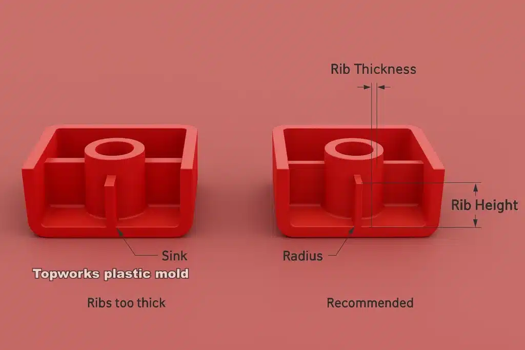
Wall Thickness
Uniform wall thickness is one of the most important factors in injection molding part design. Parts with uneven wall thickness are susceptible to warping, sink marks, and cracking caused by non-uniform cooling rates, internal stresses, and dimensional nonconformity.
- Uniformity: Wall thickness should be as consistent as possible. Variations create differential cooling rates — thicker sections cool more slowly, causing warping or deformation.
- Minimizing Thickness: Reducing wall thickness lowers material usage and cost, but walls must remain thick enough to maintain strength. A typical target range is 1–4 mm, depending on material and application requirements.
- Avoiding Thick Sections: Thick sections extend cycle time and introduce defects. Ribs and gussets can reinforce areas where wall thickness must be reduced.

Draft Angles
Draft angles are small tapers applied to vertical surfaces in the mold. They are required to allow the part to release cleanly after cooling and solidification.
- Recommended Draft: Draft angles typically range from 1° to 3° depending on the material and part size. Insufficient draft can cause the part to stick in the mold, requiring excessive ejection force and risking part or mold damage.
- Improved Ejection: Proper draft enables parts to release from the mold cavity without force, preserving surface quality and extending mold life.
Radii and Fillets
Radii and fillets eliminate sharp internal corners on injection molded parts. Sharp corners concentrate stress and increase the risk of cracking or fracture under load or impact.
- Fillets for Stress Distribution: Replacing sharp edges with smooth curved transitions (fillets) distributes stress more evenly, improving part strength and fatigue resistance.
- Flow Optimization: Internal radii also improve melt flow into the mold cavity. Sharp corners impede flow and can generate visible weld lines where two melt fronts meet.
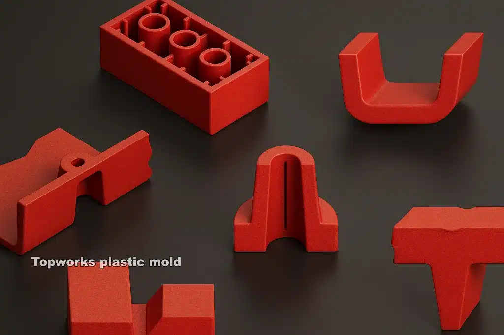
Features and Detailing
Small features, intricate details, and complex geometries increase mold complexity and cost. DFM principles recommend simplifying part geometry wherever possible.
- Avoid Small, Thin Features: Tiny holes, deep narrow grooves, and fine engraved text are difficult to mold reliably and may require secondary operations. Embossed patterns or decals are often more manufacturable alternatives.
- Simplify Geometries: Simpler parts are faster to tool, easier to run, and produce fewer defects. Every reduction in geometric complexity reduces tooling cost and cycle time.
Mold Flow Analysis
Mold flow analysis uses simulation software to predict how molten plastic will behave inside the mold cavity, identifying potential fill issues, air traps, weld line locations, and warpage risk before tooling is cut. Understanding when moldflow analysis is mandatory versus optional is an important part of a DFM strategy.
- Simulation Benefits: Engineers can evaluate different materials, gate locations, and cooling strategies virtually, identifying the most efficient approach before any steel is machined.
- Design Optimization: Analysis can flag areas of slow or uneven flow that lead to voids or warping, and can recommend optimal gate placement to minimize weld lines and air entrapment.
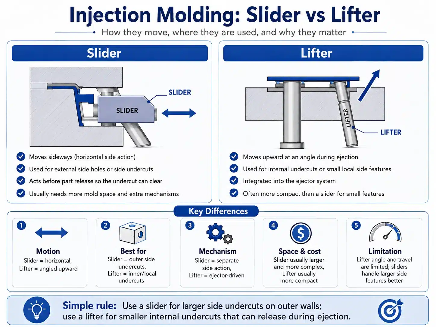
Undercuts
An undercut is a geometric feature that prevents a part from being ejected directly from the mold. Undercuts require additional mold mechanisms — slides, lifters, or collapsible cores — that increase tooling cost and cycle time.
- Minimize Undercuts: Where possible, redesign parts to eliminate undercuts. Every undercut that requires a side action adds tooling complexity and cost.
- Alternate Methods: Where undercuts cannot be eliminated, design for side-action mechanisms or consider processes such as two-shot molding for geometrically complex parts.
Ejection System Design
The ejection system removes the cooled part from the mold without damaging the part or the mold surface. Poor ejection system design is a common source of cosmetic and dimensional defects.
- Ejector Pin Placement: Pins must be positioned on non-visible surfaces where possible, and distributed to apply balanced ejection force without marking the part.
- Avoid Part Sticking: Features that cause parts to grip the mold increase ejection force requirements, leading to higher reject rates and accelerated mold wear. See the ejection system design guide for detailed recommendations.
Tolerance Control
Tight tolerances add significant complexity to mold design and increase manufacturing cost. DFM practice requires specifying only the tolerances that are genuinely required by part function.
- Design with Tolerances in Mind: Over-specifying tolerances increases tooling precision requirements, cycle time, and inspection burden without adding functional value.
- Avoid Unnecessary Tolerances: Not all features require tight tolerances. Apply tight tolerances only to mating or functional surfaces where dimensional variation directly impacts assembly or performance.
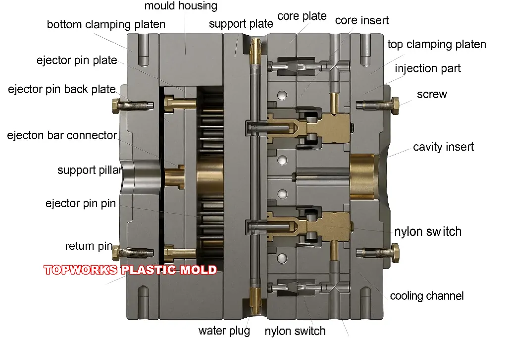
Mold Design
The mold itself is a major cost driver. A well-designed mold minimizes defect risk, maximizes production efficiency, and supports long-term maintainability.
- Tooling Considerations: Complex tooling significantly increases upfront cost and lead time. Simplifying the part design reduces mold complexity and cost proportionally.
- Modular Design: A modular mold architecture makes future design revisions and maintenance more economical, reducing the cost of engineering changes post-T1 sampling.
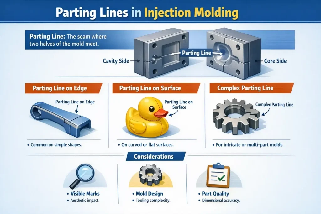
Parting Lines
The parting line is where the two halves of the mold meet. Its location must be selected to minimize visual impact on the finished part and avoid introducing structural weak points.
- Strategic Placement: The parting line should be located in a non-visible or non-critical zone. A poorly placed parting line can compromise part aesthetics or structural integrity.
- Minimize Visible Parting Lines: For consumer-facing products — particularly in electronics and automotive trim — visible parting lines are cosmetically unacceptable and must be designed out or concealed.
Cooling System
The mold cooling system is one of the largest determinants of both part quality and cycle time. Poorly designed cooling leads to warpage, dimensional variation, and extended cycle times that erode per-part economics.
- Efficient Cooling Design: Cooling channels must be designed to extract heat evenly and rapidly from all areas of the mold cavity. Uneven cooling is a primary cause of warpage and residual stress. Review injection mold cooling system design principles for channel layout and sizing guidance.
- Balanced Cooling: Uniform heat removal across the mold reduces internal stress, minimizes warping, and preserves dimensional accuracy in the ejected part.
Post-Processing and Assembly
DFM also applies to downstream operations. Parts that require extensive painting, coating, or assembly add cost and lead time that can often be reduced through better upfront design.
- Easy Assembly: Design integral features that simplify assembly — snap-fits, self-locating geometry, and built-in fastener bosses all reduce assembly time and the potential for field failures.
- Reduce Post-Processing Needs: Parts designed to net-shape specification with appropriate surface finish direct from the mold eliminate secondary operations and reduce total part cost.
Conclusion
Applying DFM principles throughout the injection molding design process is essential to producing parts that are cost-effective, reliable, and manufacturable at scale. Careful attention to material selection, wall thickness, draft angles, radii, undercuts, ejection, cooling, and tolerance specification allows engineers to extract maximum value from the injection molding process while avoiding the costly mistakes that surface late in tooling or production. According to PLASTICS Industry Association guidelines, DFM review before tool sign-off is one of the highest-ROI activities in new product development. Mold flow simulation tools complement these principles by identifying potential problems virtually before any steel is cut — a practice endorsed by SPE (Society of Plastics Engineers) technical literature as standard practice for complex injection molded parts.
Integrating DFM into the design workflow — rather than treating it as a late-stage review — is the single most reliable path to successful injection molding outcomes on schedule and on budget.
Need a DFM review before committing to tooling? Our engineering team will evaluate your part design and flag any manufacturability issues before mold build begins.

