
Bubbles in injection molding are gas- or vapor-filled voids trapped inside or just beneath the surface of a molded part. They are caused by moisture in the resin, air entrapment during filling, resin degradation from overheating, insufficient venting, or under-packing. Most bubble problems trace back to three controllable areas: material preparation, mold venting and gating, and process parameters — not the resin itself. This page explains what bubbles really are, why they matter to part performance, and the engineering decisions that prevent them.
For transparent parts (PC, PMMA, PET, optical-grade ABS), bubbles are usually an immediate cosmetic rejection. For structural parts, even sub-surface voids reduce load-bearing cross-section, concentrate stress, and become initiation points for cracks under fatigue or impact. Treating bubbles as a “process tweak” rather than a root-cause problem is the most common mistake we see in tooling and production audits.
Bubbles vs. Voids vs. Sink Marks — Diagnose Before You Fix
Before changing any parameter, identify which defect you actually have. The fix paths diverge sharply.
| Defect | Typical Location | Root Cause Family | Primary Fix Direction |
|---|---|---|---|
| Moisture bubble | Random, throughout part, often with silver streaks | Wet resin / hydrolysis | Dry material; check dryer dew point |
| Air entrapment bubble | Near last-to-fill areas, ribs, blind pockets | Poor venting / fast injection | Add vents; slow first-stage injection |
| Degradation bubble | Color-shifted, brownish edges | Excess residence time / barrel too hot | Right-size shot; lower barrel temp |
| Vacuum void | Thick sections, geometric centers | Insufficient pack / premature gate freeze | Increase hold pressure & time; review gate size |
| Sink mark | Opposite ribs/bosses, surface only | Shrinkage, no internal void | Reduce wall, balance ribs (different problem) |
The distinction between a true bubble (gas inside) and a vacuum void (shrinkage cavity, no gas) matters because the fixes are opposite — bubbles need less gas trapped; voids need more material packed in.
Moisture and Resin Drying
Hygroscopic resins — PA6, PA66, PC, PET, PBT, TPU, ABS, PMMA — absorb atmospheric moisture rapidly. Once the wet pellet hits the barrel, water flashes to steam and either creates surface splay (silver streaks) or, when trapped behind the flow front, forms bubbles inside the part.
Typical drying targets vary by resin family, but as a working reference:
- PC: typically 110–120 °C for 3–4 hours, target moisture below ~0.02%
- PA6 / PA66: typically 80–90 °C for 4–6 hours, target below ~0.1–0.2%
- PET: typically 150–170 °C for 4–6 hours, target below ~0.005% — PET is the most moisture-sensitive common engineering resin
- ABS: typically 80–90 °C for 2–4 hours, target below ~0.1%
- TPU: typically 80–110 °C for 2–4 hours depending on hardness
These are typical ranges only — always follow the specific resin supplier’s datasheet. For critical optical and structural parts, a desiccant dryer with dew point monitoring (target around -40 °C dew point) is more reliable than a hot-air hopper dryer.
Injection Speed Profiling and Air Entrapment
Fast, single-stage injection is a common cause of bubbles in geometrically complex parts. When the flow front advances faster than the vents can evacuate air, the only outcome is encapsulated gas.
The engineering response is multi-stage velocity profiling:
- Stage 1 (gate filling): slow, to avoid jetting and trapped air at the gate
- Stage 2 (cavity filling): moderate-to-fast, to maintain a uniform flow front
- Stage 3 (final fill / pre-pack): slow again, to give air time to escape through vents before the cavity seals
For bubble-prone resins (PC, PMMA, optical PET), conservative profiles with an extended Stage 3 deceleration usually outperform aggressive single-speed shots, even if cycle time increases by 1–2 seconds.
Venting — The Most Underrated Mold Design Decision
Air has to go somewhere. If the mold does not give it an escape path, it goes into the part. Venting is a mold design responsibility, not a process responsibility, which means many bubble problems cannot be solved at the press — the tool has to be modified.
General venting practice for typical thermoplastics:
| Resin Family | Typical Vent Depth | Notes |
|---|---|---|
| PP, PE | 0.02–0.04 mm | Lower viscosity; shallow vents to avoid flash |
| ABS, PS, HIPS | 0.02–0.03 mm | Watch for gas burn near last-fill zones |
| PC, PMMA | 0.015–0.025 mm | High viscosity; can tolerate slightly shallower vents |
| PA (nylon) | 0.01–0.02 mm | Low viscosity when wet — vent flash is a risk |
| Glass-filled grades | 0.02–0.04 mm | Glass scours vents; plan for re-machining |
Vents should be located at last-to-fill areas identified by mold flow analysis — typically the ends of long flow paths, blind ribs, and the tops of bosses. Where conventional vents cannot reach (deep ribs, complex 3D geometry), porous steel inserts or vacuum venting may be required. Vacuum venting is particularly effective for thin-wall optical parts and medical device housings.
Mold Temperature and Skin Formation
A cold mold solidifies the skin too fast, trapping any gas behind a frozen layer before it can migrate to a vent. The result is a sub-surface bubble that grinding or polishing cannot remove.
Typical mold temperatures by resin family:
- PC: typically 80–110 °C
- PMMA: typically 60–90 °C
- ABS: typically 50–80 °C
- PA66: typically 80–100 °C (higher for glass-filled or thin-wall)
- PET (optical): typically 100–140 °C
Running the mold at the lower end of the supplier’s range to shorten cycle time is a frequent root cause of bubbles in thick-section parts. The cost trade-off — slightly longer cycle vs. scrap rate — is almost always in favor of the warmer mold.
Gate Location, Size, and Type
Gate decisions affect bubbles in two ways. First, gate location determines flow front direction — a poorly placed gate creates converging flow fronts that trap air mid-cavity (causing both bubbles and weld lines). Second, gate size determines how long the cavity stays open for packing — undersized gates freeze early, locking in voids before pressure can compress them.
For thick-section transparent parts, the gate should generally be located on the thickest area, allowing the flow front to progress from thick to thin. This sequence pushes air toward the thin-wall last-fill zones where vents can evacuate it.
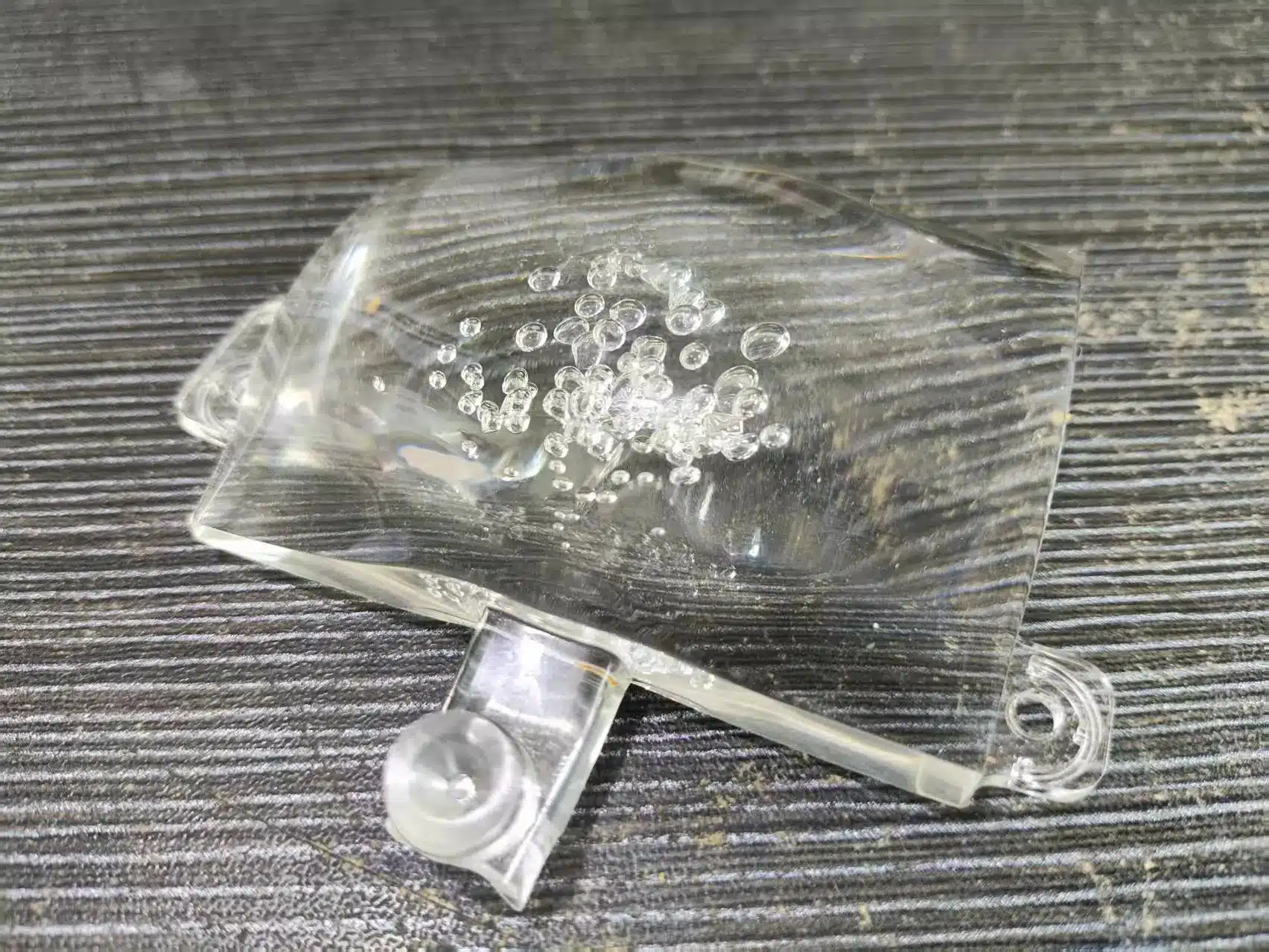
Case Reference: Curved PC Part with Persistent Bubbles
On a curved transparent PC component with bubbles concentrated along the curve, the resolved approach was:
- Drying: PC dried at 120 °C for 4 hours before each run
- Barrel temperature: reduced screw and nozzle temperatures to the lower half of the supplier’s range to prevent premature degradation
- Gate strategy: small cold-runner gate retained, but injection profile re-engineered so the bubble would migrate back into the sprue/runner system rather than the part
- Process profile: first-stage injection position moved earlier (more material under controlled flow), first-stage speed reduced, back pressure increased moderately to compress any entrained gas
The principle worth taking from this: when bubbles cannot be eliminated, they can sometimes be relocated — pushed into the runner or sprue where they are scrapped, rather than left in the cavity. This is a recognized technique for high-value transparent parts where mold modification is not immediately possible.
When to Bring in a Mold Supplier
Process-side fixes (drying, speed, temperature) should be exhausted first because they are reversible and cheap. If bubbles persist after a structured process review, the issue is almost certainly in the tool — venting, gate location, or cooling layout. At that point, mold modification or, for high-volume production, a redesigned tool becomes the more economical decision than ongoing scrap.
Engage a mold supplier when: (1) you have a recurring bubble defect tied to specific cavity geometry; (2) mold flow analysis shows trapped-air zones with no nearby vent; (3) gate location is causing converging flow fronts; or (4) you are sourcing a new tool for a transparent or thin-wall part where bubbles would be a launch-blocking defect.
Frequently Asked Questions
Are bubbles in injection molded parts always a defect?
For transparent or cosmetic parts, yes — bubbles are typically a rejection. For non-cosmetic structural parts, small sub-surface bubbles in non-critical areas may be tolerated, but they always reduce load-bearing cross-section and should be evaluated against the part’s mechanical specification.
How do I tell the difference between a bubble and a vacuum void?
A bubble contains gas and is usually round with a reflective inner surface. A vacuum void is a shrinkage cavity in thick sections with an irregular shape and no internal gas. Cutting the part open and inspecting the void surface usually distinguishes them. The fixes are opposite, so getting this right matters.
Can I eliminate bubbles by increasing hold pressure?
Higher hold pressure helps with vacuum voids and small near-gate bubbles, but it cannot evacuate gas that is already trapped behind a frozen skin or in a poorly vented area. If higher hold pressure does not resolve the issue within a reasonable range, the root cause is likely moisture, venting, or gate location — not packing.
Why does my PC part have bubbles even after drying?
Drying alone is not sufficient if the resin re-absorbs moisture between the dryer and the hopper, if the dryer dew point is too high, or if barrel temperatures are degrading the PC. Verify dryer dew point, minimize the time between drying and processing, and check that barrel temperatures are in the lower half of the supplier’s recommended range.
Does mold venting need to be modified for different resins?
Yes. Vent depth must be matched to the resin’s viscosity at processing temperature. Low-viscosity resins like nylon will flash through vents sized for PC or ABS. When a mold is repurposed for a different material, venting should be reviewed as part of the changeover.
Is vacuum venting worth the cost?
For high-value transparent parts, thin-wall optical components, and medical housings, vacuum venting often pays back through reduced scrap and faster qualification. For commodity parts with conventional geometry, properly designed passive vents are usually sufficient.
Need Help Resolving a Bubble Defect?
If you are seeing recurring bubbles in a current production tool, or designing a new transparent or thin-wall part where bubbles would block launch, our engineering team can review your part geometry, gate strategy, and venting layout and recommend the minimum-cost path to a clean part. We work with product development teams, procurement organizations, and OEMs in Europe, North America, and Australia.

