
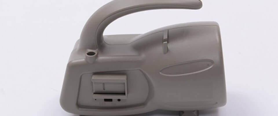
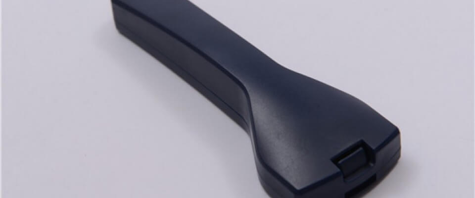
To optimize entire injection molding manufacturing process, Design for Manufacturability (DFM) is recognized as an effective approach that integrates engineering and production during the plastic design stage to yield high-quality products that satisfy regulatory mandates at reduced cost for end-users.
Injection Molding DFM Explorer
Twelve adjustable design elements that determine whether a molded part builds cleanly, cycles fast, and looks right. Click any tab to compare good vs. bad practice.
Draft Angles
Taper on vertical walls so the part releases from the steel
Every surface parallel to the direction of mold pull needs a slight outward taper. Without it, the part wedges against the steel and refuses to eject cleanly — you get scratches, stress whitening, or fractured walls. Draft also extends mold life by reducing scraping load on polished surfaces.
Designer rules of thumb
- Minimum 0.5° on smooth surfaces; 1–2° is industry standard
- Add 1° per 0.025 mm of texture depth
- Heavy leather or shark-skin textures may need 5°+
- Only surfaces perpendicular to mold opening need draft
- More draft is almost always better if the envelope allows
Corner Radii & Fillets
Round every inside corner to relieve stress and guide flow
Sharp internal corners are the fastest route to part failure. Stress concentrates at the apex during cooling and again under load, initiating cracks. They also choke flow and create cooling differentials. Outside corners matter too — a small round prevents steel chipping and flash-prone feather edges.
Designer rules of thumb
- Inside radius ≥ 0.5 × wall thickness (minimum); 0.75× is better
- Outside radius = inside radius + wall thickness (keeps wall uniform)
- Never design a true 0° corner on any feature that matters
- Fillet the base of every rib to prevent sink and boost stiffness
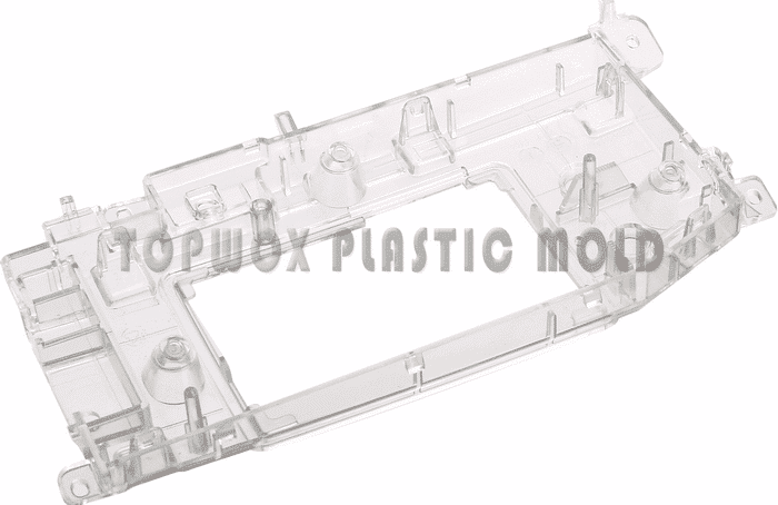
Ribs
Stiffen parts without thickening walls
Ribs add rigidity without bulking up the main wall — critical because thick walls sink, warp, and lengthen cycle time. But ribs have their own rules. Too thick and they sink themselves; too tall and they won't fill or they buckle; too close together and the steel between them can't cool.
Designer rules of thumb
- Rib thickness: 0.5–0.6 × adjoining wall thickness
- Rib height: ≤ 3 × nominal wall thickness
- Rib-to-rib spacing: ≥ 2 × wall thickness
- Base fillet: 0.25–0.4 × wall thickness
- Side draft: minimum 0.5° per side, 1° preferred
Bosses
Mounting features for screws, pins, and inserts
A boss is any projecting cylinder used for fastening or alignment. The common mistake is modeling it as a solid lump, which creates a thick section that sinks, warps, and cools slowly. Design a boss as a tube whose wall matches the rest of the part, supported by gussets where it joins the main wall.
Designer rules of thumb
- Outer diameter ≈ 2 × screw diameter (self-tapping)
- Boss wall ≤ 0.6 × nominal wall to avoid sink
- Use 3–4 gusset ribs at the base for load transfer
- Draft: 0.5° external, 0.25° internal
- Never leave a boss free-standing — tie it to a wall or floor
Undercuts
Features that block straight ejection
An undercut is anything that mechanically locks the part to one half of the mold — a snap feature, a side hole, an external groove. Resolving them requires side actions, lifters, or collapsible cores, which dramatically raise tooling cost and cycle time. The first question in DFM review: can this undercut be eliminated?
Designer rules of thumb
- Redesign snap fits as through-holes where possible (pass-through coring)
- Move side holes to parting-line direction if geometry allows
- Accept a 2–3° ramp instead of a true 90° undercut (flex-release)
- If side action is unavoidable, minimize travel distance
- Hand-loaded inserts can solve rare undercuts cheaply at low volume
Gate Location & Type
Where molten plastic enters the cavity
The gate controls flow direction, pressure distribution, weld-line location, and how visible the gate vestige will be. Get it wrong and you see sink, voids, jetting, or knit lines straight across the cosmetic face. Get it right and the part fills uniformly with the scar hidden.
Designer rules of thumb
- Gate into the thickest section first — flow goes thick to thin
- Place gate to minimize flow length and balance pressure
- Avoid gating onto thin ribs, bosses, or unsupported walls (jetting)
- Edge gate: simplest and cheapest; small vestige remains
- Tunnel / submarine gate: auto-trims at ejection, cleaner cosmetics
- Hot-tip gate: zero runner waste, ideal for high volume
Parting Line
Where the two mold halves meet — and always show
The parting line is where the two mold halves come together, and it will almost always show as a faint seam or flash on the finished part. Every part has one — the question is where you put it. A bad parting line runs across a polished A-surface; a good one disappears into an edge, a radius, or a recessed feature.
Designer rules of thumb
- Route the parting line along a natural edge, step, or rim
- Avoid parting lines that cross cosmetic A-surfaces
- Keep the line in a single plane when possible (cheaper mold)
- Stepped or profiled parting lines cost more but hide the seam
- Consider whether flash will be trimmed or accepted as-is
Ejector Pin Placement
Where the part gets pushed out of the mold
Ejector pins leave small circular witness marks — raised or depressed — on the surface they contact. Place them on cosmetic faces and every part ships with blemishes. Place them on the B-side and you never see them. Pin size and count also matter: too few or too small and you deform thin walls or leave drag marks.
Designer rules of thumb
- Always eject against the B-side (non-cosmetic) surface
- Put pins on ribs, bosses, and flat non-visible flanges
- Minimum 3 pins for a typical part; more for larger or flexible ones
- Larger-diameter pins distribute load better than many small pins
- Mark "no-eject zones" on your print for cosmetic areas
Coring
Hollow out thick sections to keep walls uniform
Thick sections are the enemy of injection molding. They cool slowly, creating sink marks outside and voids inside as the skin solidifies before the core. The fix is counterintuitive: carve the thickness out from the back, turning a solid block into a shell with uniform walls. The part keeps its envelope shape but molds cleanly and cycles faster.
Designer rules of thumb
- Any section thicker than 1.2× nominal wall is a candidate to core
- Core from the side hidden in the assembly
- Replace solid handles, bases, and pads with ribbed shells
- Uniform wall = uniform cooling = minimum warpage
- Cycle time drops dramatically when thick sections disappear
Hole Design
Through-holes vs blind holes and core-pin limits
Every hole in an injection-molded part is formed by a steel pin in the mold called a core pin. Long, thin core pins are cantilevers — they deflect under flow pressure and drift out of position. That's why blind holes have strict aspect ratios and why through-holes (supported on both ends) are always preferred when geometry permits.
Designer rules of thumb
- Through-hole depth up to 6× diameter (supported both ends)
- Blind-hole depth ≤ 3× diameter (unsupported pin)
- Minimum distance from hole edge to part edge: 1 × wall thickness
- Chamfer or radius the hole opening to ease flow around the core
- Hole diameter ≥ 1.5 mm for reliable pin strength
Text & Logos
Part numbers, warnings, and branding molded into steel
Text on a molded part is inverted into the mold steel. If letters stand proud on your part, they're engraved into the mold — a single durable cavity. If letters are recessed into your part, they're raised on the mold — thin fragile steel that chips off. That's why raised text is the industry default.
Designer rules of thumb
- Raised text on the part (engraved in the mold) — preferred
- Letter height: 0.4 – 0.8 mm above the surface
- Line width: ≥ 0.25 mm; stroke ≥ 2× smallest EDM feature
- Sans-serif molds better than serif — serifs snap off
- Align text with draft direction; add 10–15° side draft on letters
- Avoid fonts under 2 mm cap height on textured surfaces
Surface Texture
SPI finishes and their draft-angle demands
Textured surfaces look premium and hide minor defects, but every texture cuts into the mold steel — and the part has to climb over that texture during ejection. Without enough draft, the texture drags the part like sandpaper. Texture depth and draft angle are tightly coupled; you cannot specify one without considering the other.
Designer rules of thumb
- Add 1° of draft per 0.025 mm (0.001″) of texture depth
- Light grain (SPI B-1, B-2): 1–2° draft minimum
- Medium grain (SPI C-1, C-2): 3–4° draft
- Heavy leather or stone texture: 5–7° draft
- MoldTech and VDI are common alternatives to SPI grades
- Lock texture spec with your molder BEFORE finalizing geometry
One key aspect of DFM lies in performing concurrent FMEA and extensive analysis on plastic components towards assessing risk probability – this massively helps maximize all attainable benefits from practicing DFM early enough during product development processes.


Intricate cases of applying DFM require technical competence in injection dressing skills that fuse well with other techniques like FMEA for an even better outcome – partnering with a qualified DFM-based injection molder adds even more value too! Detailed designs have considerations made with shape and tolerance in mind before advanced systems or standards get integrated.
Establishing the right tolerance level for a part depends on how it functions – anticipating potential failures and adopting methods to prevent them proactively can lead to significant cost-savings in both money and time.
Therefore, employing performant FMEA-based risk assessments is crucial towards early identification of problems and efficient problem-solving methods.
FEEDBACK ON THE DESIGN PROCESS IMPROVED
When it comes to detailed design, shape and tolerance are two key considerations. Shape is only relevant when advanced systems or standards are involved. In order to establish tolerance one must assess how it impacts the function of a particular part.
Taking a proactive approach to failure prevention can help reduce both time and costs by anticipating issues during the design process or plastic part analysis.

The ultimate goal is to design and manufacture reliable products that meet all required specifications. By evaluating, documenting, and prioritizing corrective actions based on failure modes engineers can use FMEA to optimize product performance during the design phase. Through DFM methods – with FMEA being particularly effective – risk probabilities can be controlled during the design phase.
PROCESS CAPABILITIES ALIGNED WITH TECHNICAL SPECIFICATIONS
This builds confidence at every stage of the process from conception through completion.
Analyzing plastic flow and cooling during injection molding requires tool simulation software.
Understanding how plastic behaves within the tool is critical for ensuring that part design elements such as wall thickness, draft, gate locations, geometries etc. are appropriate.
Many software options exist for this purpose with each project requiring selection according to specific requirements so as to enhance production efficiency while also improving overall quality.
TOOL BUILD: REDUCED CHANGES
DFM analysis reduces costs by managing tool build changes post tool build stage. Engineers can use test results obtained previously in order to help manufacturers reduce costs and save time by addressing potential issues early on during planning stages.
In order to minimize changes after toolbuild stage is completed and maintain maximum efficiency practical solutions must be sought out quickly when potential project stumbling blocks occur during initial planning phases.
FABRICATION WITH LESS COMPONENTS, AT A CHEAPER PRICE, AND WITH FEWER COMPONENTS
When attempting automation cost reduction efforts, using fewer components is key in reducing material requirements and ordering frequency which consequently lowers costs incurred in performing these operations. This efficient approach also makes inventory management more manageable for end-users while enhancing their field service experiences too.
DFM simplifies fabrication by substituting materials which in turn strives toward lowering costs while improving series of processes such as assembly process fluidity along with optimizations achieved through proper geometry formation enhancing general part quality at an economical price.
WHO GETS THE MOST OUT OF DFM?
The versatility of DFM means it is appreciated by various business specializing across diverse fields although its most significant value derives from its upfront evaluation during new product development life cycle.
For lack-of-experience designers working on plastic parts designs, partnering with injection molders possessing professional skills greatly enhances their communication ability by providing access to expert level knowledge combined with cutting-edge technology enabled results-driven solutions.
DFM-Based assessments also help in estimating final cost per part and overall manufacturability, culminating in optimized design schema to establish an efficient production schedule. Understanding the importance of “Sweet Spot” during design reviews which are done through detailed 3D models (CAD files) expedites the DFM analysis process.
DFM GUIDANCE FROM TOPWORKS – WHY?
Whether you belong to the medical industry or automotive sector or any other industry type seeking product solutions, it is important to conduct a DFM study by a certified injection molder. This study helps immensely by providing upfront feedback resulting in meeting project specifications while keeping cost-control intact.
Our at Topwoks’ approach towards DFM analysis is collaborative rather than just being an exhaustive process that achieves no solution-focused outcome. We pride ourselves on our multi-disciplinary approach with an experienced team comprising of toolmakers, manufacturing engineers, coordinate measuring machine (CMM) technicians as well as quality & design engineers for plastic parts all working collaboratively while striving towards desired outcomes for clients’ products using this method along with our strong experience in DFM solutions including FMEA analysis.

