Troubleshooting Product Defects in Injection Molding–flash,short shot,silver streaking…

Troubleshooting in the injection molding field serves as a pursuit that comes about to figure out the explanation for and remedy for, faults present in a molded component.

This process generally happens whilst components are made and come about, once the normal manufacture of appropriate components is disrupted due to the unpredictable output of a number of faulty, unsatisfactory components.

The individual executing the troubleshooting job might be a worker, an operation tech, a plastics engineer, or perhaps a supervision staff.

injection molding troubleshooting

But, that person is still known as the “troubleshooter,” although that actual title seldom appears as a job description.

Sometimes, troubleshooting comes about when evaluating components earlier created, for example when components are sent back for the reason that they failed to appropriately accomplish their designed function.

Generally, this case is researched working with failure analysis methods but troubleshooting could be also known as about.

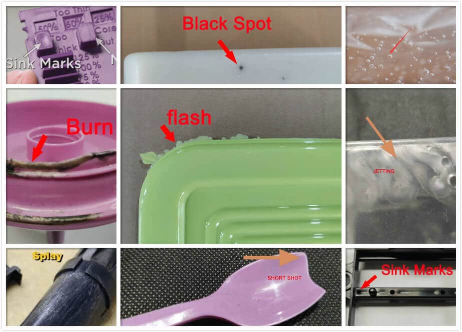
  • The Causes Of Faults?

the flaws could possibly be traced to issues with a number of the next 4 items:

  1. the molding press;
  2. the mold;
  3. the plastic resin;
  4. and the molding press operator.

Probably the most fascinating matter was how much these points contributed to the explanation for the faults.

The easiest reason behind faults in molded components stands out as the molding press itself, which happens to be 60% on a regular basis.

This is accompanied by 20% of the faults due to the mold, 10% due to the material, and just 10% due to the operator.

As opposed to what the research discovered, the majority of people in the profession have believed that the most prevalent reason behind faults is often the resin, with the worker showing up in a close position.

Nonetheless, as the research turned out to be, the particular most common reason behind faults is the molding press, and then the mold.

Therefore, when trouble-shooting, originally to hunt for an answer to a deficiency issue is the machine since the chance is about 60%.

[tabs] [tab title=”Black Specks”]

black specks

  • Sprue Bushing Nicked, Rough, or Poor Seating 

In the event the sprue brushing is nicked, coarse, not really sitting, it might bring about materials to decay.

The reason behind this can be that the material is caught in place (until it finally overheats) within a section of the mold that maintains a high temperature.

The degraded material turns fragile and may destroy to be loose, coming into the softened stream and appearing as dark-colored dots or streaks.

Examine the interior surface area of the sprue bushing.

Clear away any grazes or other flaws. Examine with thin paper to check if the radius of the nozzle is about (or small compared to) that of the sprue bushing.

  • Burnt Materials Due to Inappropriate Ventilation

Incorrectly venting areas appear with white ashing around the mold steel or the charring of the material.

This can be from the burning of air captured inside the mold and squeezed to the situation of combustion.

Track down vents in the mold at areas 1 in. (25.4 mm) away from each other all along the circumference of the cavity on the static half.

Whenever extra venting can be done, get it done.

You cannot find any such issue as an excessive amount of venting.

  • Abnormal Dwelling  in Barrel

Each cycle, the barrel capacity should be used up about 25%-80%

Should the plastic dwell in the barrel in excess of the standard time, it is going to commence to deteriorate.

This destruction brings about carbonized plastic material which seems like tiny dark clusters.

These may be transported with the softened stream and make an appearance as stains or lines on the component, noticeable on the exterior of solid components and see-through components.

The remedy is to install the mold into a competently-sized press.

  • Dirtied Raw Material

Contamination is the consequence of unclean and merged regrind, wrongly flushed hoppers, open material storage units, and also sub-standard virgin substances as offered by the producer.

The treatments consist of working with high-quality providers, making use of fine house cleaning routines, and effectively coaching material handling employees

[/tab]

[tab title=”Blisters”]

injection molding

  • Insufficient Temperature Control

The mold should work in a particular temperature array for particular plastic material.

Insufficient cooling channel circulation can lead to a few regions of the mold cooling quicker when compared to other locations.

These low-temperature fields will result in the plastic to the skin, while the remaining plastic continues to be solidifying.

It will develop emptiness in these spaces to create a blister.

Ensure that waterlines are situated near to the cavity image, and they accurately stick to the cavity shape.

The concept should be to keep in mind that circulation of the cooling channel goes over the mold, nevertheless particularly in the cavity image region.

  • Appropriate ventilation

Appropriate ventilation is extremely important for developing a mold.

The proper width, position, form, and quantity of vents have to be considered and studied on the mold concept phases.

In the event that inadequate venting occurs, captured air is not able to get away from the mold and can develop into the emptiness that develops into blisters.

Vents ought to be located at 1 in. (25 mm) intervals around the parting line. Additionally, the runner ought to be cut for venting a similar way.

Air that is stuck in the runner will be pressed into the cavity and accumulated there.

  • Lacking Back Pressure

Given that the material is dried in the heating cylinder, air would result in being caught inside melt. The purposes of back pressure could be to compel this specific air outside prior to it being shot into the mold.

Backpressure needs to be set up at Fifty psi (345 kPa) and enhanced in steps of Ten psi (69 kPa) before suitable
adjusting is attained, however in no way it is more than three hundred psi (2,068 kPa).

[/tab]


[tab title=”Blush”]

  • Small Sprue Dimension

In case the sprue is smaller sized, it leads to plastic getting cold (solidify) too quickly soon after it makes its way into the mold and may bring about blush, particularly in a sprue-gated component.

Blush found at a surface gate implies the gate may perhaps be thinner, bringing about a similar influence.

Guarantee the sprue opening at the nozzle tip is adequate.

These details can be acquired from the provider of the plastic supplier.

Hard materials (just like poly-carbonate) call for larger diameters intended for better flow.

Likewise, look into the gate height.

The fabric provider can offer the range of height necessary for a particular material.

Make sure a rectangular gate has ample radii.

  •  Low Temperature

In case the mold temperature isn’t high enough, the movement of the smelted materials is restricted and the material stiffens prior to it fulfills the mold.

Blush (cloud finish) will show up in the final place to be packed, normally the entrance. Enhancing the mold temp
enables the material to move a greater distance and pack competently.

[/tab]

[tab title=”Bowing”]

  • Poor Gate Position

Frequently, the explanation for bowing in a molded component would be that the gate is situated in a skinny section to fill farther thicker sections.

This brings about irregular molecular dimensions because of the trend for the fabric to cool off and solidify as it attempts to move through the thin sections initially.

Once getting smaller, the molecules in the thicker sections reduce in size more than the molecules in the thin sections, which triggers the component to twirl and bend.

Gates must be placed with ideas at heart: gate towards the thicker portions, and centralize the movement of material.

Setting a gate on the thicker sections enables the material to fully occupy the mold cavity before it cools and contracts.

A centralized stream enables an excellent disposition of material over the cavity image.

The better these rules-of-thumb are implemented, the reduced bowing will be.

  • Unequal Mold Temperature

An injection-molded component should be permitted to cool in a mold keeping constant temperatures.

If you will find “hot-locations” inside the mold, those fields could be the ultimate to cool and the resultant transmission in shrinking among those hot-locations and other fields will bring about the deformity of the component (bowing).

Designing and building the mold to make both the moving and static half have the identical efficiency for cooling down.

This will likely reduce the tendency for the plastic component to stick to whatever half is hotter.

Additionally, prepare the cooling pipes to make sure that you will see a maximum of a 10° F (6° C) discrepancy between any specific two places of the mold.

  • Quick Mold Opens

To raise the number of products developed within one hour, molders might often raise the rate at which the clamp opens soon after the molding cycle.

If plastic mold opens too quickly, it will have an inclination for the component to stick to the cavity part of the mold. When the mold continuously moves, the component will return back on top of the core half and the consequence would be a bowed component because of this deformation.

The remedy is to ensure the initial 1/4 in. (6.35 mm) of “mold open” is scheduled at a slow rate. The rest of the opening step can subsequently be set up considerably quickly.

  • Unsuitable Coping with

Easy it really is that the worker has wrongly maintained injection molded components after ejection.

If components are packaged for transport too quickly subsequent to creating, the heat that may be kept within them most likely are not able to go away competently and they could take on a bowed position.

Additionally, some employees might not exactly take care of the components in the identical manner as the other operator performs. Appropriate coaching is necessary to solve that problem, and investigation wrapping operation ought to be carried out to reduce the drawback.

[/tab]


[tab title=”Brittleness”]

  • Gate and/or Runner Limitations

Gates and runners which might be smaller sized, or have unnecessary abrupt corners, may result in shearing and ripping off the plastic when it passes through them.

It will create a break up of layers during the plastic movement.

These segregated layers will cool down very fast rather than manage to stitch back again.

The outcome will likely be a fragile molecular connection displayed as brittleness on the component.

Take a look at the gates and runners to make certain they are designed to the advice of the plastic material company.

Every single plastic resin contains a particular prerequisite relating to gate and runner pattern, and all these must be implemented as thoroughly as possible.

  • Substantial Moisture content

All substances require a bit of moisture to effectively work, commonly in the range of 1%.

A few substances like nylon material and ABS are hygroscopic in general and easily soak up water coming from the environment, despite initial drying out.

These are generally problematic materials to hold dried. Humidity leads to brittleness for the water droplets transform into vapor when heated within the injection equipment and this kind of vapor blows up above the entire soften stream, leading to voided spots.

These voided spots are not appropriately fused and instantly crack, should they be exposed to any kind of physical forces right after ejection.

Some materials (particularly hygroscopic) might benefit from conditioning after molding to substitute the humidity deleted during the molding procedure.

Nylons here are an example, usually have to be treated through either annealing in 305 F (155 C) glycerin for Several hours, or staying still for 4 nights within enclosed bags full of water.

With no treatment, this plastic part might be breakable.

[/tab]


[tab title=”Voids”]

injection molding

  • Too thick wall

If a plastic component involves various wall thicknesses (rather than one constant size), the thicker areas will cool down (and harden) finally.

You will see a pressure reduction in those thicker portions because they carry on to cool even after the thin sectors have solidified.

The plastic will draw over the sturdy region and result in an emptiness in the thicker location.

In the event the emptiness is located on the exterior of a component, it seems to be a sinking spot.

If it is under the exterior, it seems like a bubble.

The ideal remedy (though costly) is the use of core-outs to help to make the thicker wall thinner.

On the other hand, if you can, redesign the wall size to ensure the thick region is no greater than 25% thicker compared to the thin sector, it will reduce the void.

  • Unnecessary humidity

Air can be stuck inside the material as the molding procedure advances and manifest as voids within the molded component.

The humidity basically changes to vapor through the heating procedure and can’t get away from the material, therefore it builds a gas pocket which appears as an emptiness.

The straightforward option is to effectively dry the resin prior to production.


[/tab]


[tab title=”Burn Marks”]

burn marks

  • Inappropriate Venting

Ventilation slot is located in molds to discharge any sort of gases or captured air that may be harmful.

Should the ventilation slots are not in-depth enough, or large enough, or if you discover insufficient ventilation, the air is condensed to ignite before it is all expelled.

Air burns up to char the nearby material.

Vents should be no less than .125-in. (3-mm) large.

The venting width must not be in excess of .125-in. (3-mm) .

Closed portions, including the lower side of holes, needs to have ventilation made on the top of ejector pins there.

There needs to be plenty of ventilation on the parting line, the length should be equivalent to 30% of the length for
the parting line circumference.

Therefore, a 10-in. (25-mm) long P/L circumference could have 11 vents, each that dimensions .25-in. (3-mm) wide (3 in. [76 mm]total).

One more rule-of-thumb suggests that a vent ought to be located at 1-in. (25-mm) between each throughout the parting line land.

  • High amounts of Regrind

The usage of regrind must be restricted, particularly when making use of heat-sensitive resins like Pvc material. Regrind resin is likely to take in heat within the barrel at a less quick speed when compared with virgin, because of the unnatural surface types and bigger dimensions of the regrind flakes.

This makes an extended dry time, which leads to the virgin particles getting too hot and decaying. The destruction gives the shape of burnt flakes which are transferred with the softened resin inside the cavity.

Restriction regrind is a maximum of 4.5 or 11%.

Should the injection volume not be so big (below 20% of barrel size) it might want zero regrind in any way.

A possible solution would be to commence with almost all virgin and little by little increase regrind usage, the regrind at 2% steps till burning takes place.

Subsequently, decrease back 2% measure and make use of the resultant proportion for long-run production.

[/tab]


[tab title=”Clear Spots”]

  • Mold Crack

A potential reason for obvious spots in a molded component is a broken mold cavity.

If the crack hails from a water line, water can be dripping into the cavity and it might be caught as tiny droplets, showing up as obvious spots on the molding.

The seepage is probably not noticeable with the mold opened and could just take place in the event the
mold is shut and it would be subject to clamp pressure.

Damaged mold housing can be fixed, however, the reason ought to be identified.

It is feasible that a water line was located too close to a cavity set, therefore deteriorating the steel alloy between them.

On the other hand, a cavity was probably destabilized at the time of the hardening. Obviously, there is a selection of conceivable causes.

It can be required to change the complete mold.

If a waterline has fallen apart open, it is possible to put in a Cu conduit in the waterline and employ it as a cooling path to be a short-term restoration.

If welding can be used to fix a damaged cavity or mold housing, the welding needs to be done merely by a reliable person, skilled with this particular sort of welding.

  • Low Temperature In Barrel

Very low barrel temperatures bring about an inappropriate mixing of substances because of unmelted grains.

These grains go through the softened resin and finally into the cavity. When it comes to translucent components molding they manifest as transparent spots, but even within solid components, they may present close to the surface area.

Slicing a solid component open will disclose the spots as voids.

Raising barrel temp will decrease the inclination for unmelted grains. An increasing amount of 15 F (8 C) steps and enables the temperatures to become stable (10 cycles) before raising repeatedly.

  • Unpredictable Cycle Time

Inconsistent cycling of the equipment can cause inconsistent heating located in the barrel, leading to hot points and cold points.

Resin coming from the cool points may keep going through the entire softened resin without getting appropriately heated and may manifest as transparent points in translucent components.

Coaching the workers and clearing up the significance of uniform cycles must be coupled with illustrations of faulty components operated in the course of irregular cycling.

[/tab]


[tab title=”Cloudy Visual appeal Or Gloss”]

  • Unequal Packing of impression

Unequal packing can typically be traced to incorrect gating, runner dimensions, or position.

The material goes into the impression at the incorrect location, which doesn’t let the material be filed against the mold metal wall.

Molten stiffens without copying the mold surface, and this looks like a foggy spot.

There can be another likelihood that a particular part of the molding exterior wasn’t finished as the other places.

This might produce a foggy visual appeal in that spot.

Make certain the mold is correctly finished. If that’s the case, look into the appropriate gate specifications, quantity, and placement for a distinct item pattern and material from the material supplier.

[/tab]


[tab title=”Contamination”]

injection molding

  • Abnormal Lubrication

Molds, featuring motions like slides and lifters, call for routine lubrication to guarantee steady manufacturing. Nevertheless, sometimes, the molder realizes it is problematic to find lubrication areas and overload them after being greased.

An excessive amount of lube can transfer to the impressive image and fail the shaped component.

Develop and build motions having lubrication spots and accessories that are conveniently available to the molder. This can let the molder grease only when necessary to minimize the sum of lubes put to use.

  • Inappropriate Regrind

Regrind may consist of quite a few impurities like food items pots, soda stains, debris and mud flakes, and some other materials.

Normally, this is because of the negative cleaning process and negative resin-controlling processes. This problem
may be considerably diminished by appropriate coaching of staff, remarkably noticeable brands of regrind canisters, appropriate marking of garbage canisters to distinguish them all from resin canisters, firm fitting shields for regrind (and any resins) material storage units, appropriate maintaining of regrind devices, and caution in the course of material changeovers.

  • Negative Housekeeping

A worker can bring about pollution with behavior like dining at the molding machine section.

Spud chip and soda are typical reasons for resin.

Dust particles coming from mopping can get into the hopper when not secured.

And, in unusual instances, employees have been recognized to “force a break” by purposely tossing waste in the hopper.

Workers ought to be directed on the significance of sustaining positive housekeeping procedures and managers should be presented to similar specifications also.

[/tab]


[tab title=”Cracking”]

  • Inadequate Draft or Polish

Draw angles need to be at least 1 per edge to help the effortless elimination of the component away from the mold. Ejector pushing can result in broken components if lower than that is utilized. Additionally, coarse impression surfaces (and some other undercuts)
produce a pull on the component when it ejects. This may trigger damage if the push force is raised to drive the component on this coarse surface.
All sidewalls need to be `designed to the maximum level achievable, but to 1 minimum.
Carefully consider, and get rid of undercuts developed by peened parting lines or any other shut-off locations. Impression surfaces should obtain a superior gloss once the mold is made
and re-polished when the requirement occurs.

  • Built-in Stresses

Stresses may be built into an item via the molding equipment by too much shot volume or too rapid injection speed. The resins are shot and retained resistant to the restraining walls of the mold impressions.

Even after the component is expelled out of the mold, the cooling down procedure carries on (for about four weeks) and the remarkably stressed resins can start to alleviate.

If the skin of the component is not still sturdy adequate, it’s going to break up by means of cracks.

Reduce steadily the shot pressure and rate until minimum figures which will productively complete the component. This minimizes the inclination to stress in the plastic mold.

[/tab]


[tab title=”Clear Spots”]

[/tab]


[/tabs]

[tabs]

[tab title=”Delamination”]

injection molding

  • Unnecessary Mold Release

In case a mold release should be used in any way, it is crucial to restrict its usage.

An excessive amount of mold release will result in the mold release going into the molded parts. This may sustain
the materials from binding and bring about delamination.

Make mold release clear of presses except if essential then simply work with being a short-term restore before the basis for the adhering may be amended.

Look into the mold and trial components to find out how come a component is staying. Try to find and fix the undercuts produced by destroyed parting lines.

Check out core pins, searching for mushroomed tips. See whether polishing needs to assist the molded component
unleash out of the mold.

  • Foreign Resources or Additives

When a pigment is utilized to tint the plastic, it may not be appropriate, for example, if where the detergent is employed for the producing of the pigment.

When a color concentrate is employed to tint the plastic, it ought to be of a substance suitable for the basic plastic resin.

And, in the event that unintended blending of two mismatched resins has taken place, they won’t bind. In all these instances, nonbonding of the substances employed will lead to delamination of the molded ranges of the completed item.

Seek the advice of vendors of any additives to guarantee the suitable standard will be utilized. Additionally, make sure all resins are appropriately determined to make certain that mismatched resins have not been blended.

[/tab]

[tab title=”Discoloration”]


  • Incorrect Mold Temp

Generally speaking, an overheated mold will lead to the resin remaining smelted for a longer time and make it possible for the compounds to bundle firmer.

The consequence is a really compacted component that shows up darkish because of denseness. Alternatively, a cool mold will result in a reduction in shininess due to the fact the substance cools down prior to it being compelled versus the mold surface.

This may result in a reduced dense component, that will seem to be lighter.

The waterlines size ought to be sufficient to allow for the appropriate circulation of liquid necessary to deliver turbulence with a proper Reynolds value.
Less value will lead to poor water circulation and unreliable temperature regulation.

When the stream turns into laminar, the mold temps will go up and down over the operation and bring about components of different gradations of color.

  • Inappropriate Mold Temp

Generally speaking, a hot mold will result in the resin remaining melted for a longer period and make it possible for the molecules to bundle tighter.

This produces a really compacted area which shows up darkish because of that solidity. On the flip side, a cold mold will result in a reduction in gloss as the resin cools down prior to it being compelled as opposed to the mold surface, and this leads to a lower dense component which will show up brighter.

The mold temp needs to be modified, with the restrictions established for the specific plastic, to the situation where the resin has the appropriate color and gloss attributes.

Remember that the color will alter a little bit once the component is entirely cooled.

  • Contamination

The resin may be seen discolored should it be afflicted with quite a few things, for example, incorrect regrind, substance strands, thermally deteriorated resin, and food contaminants.

Additionally, if the whole shot has been subjected to unnecessary temperatures, it will be dim.

Appropriate housekeeping will eliminate the majority of this kind of discoloration, and carefully handle of appropriate molding temps will eliminate the remainder.

[/tab]

[tab title=”Flash”]

flash

  • Poor Fitting Shut-off Lands

As time passes, the main plane of the P/L may produce a NONPARALLEL state. It may be due to a lot of reasons, such as impressions that have pushed into the mold, or flash that is in the position to stay on the P/L land, finally developing depressed ends.

Check out the parting line, in search of broken places, particularly those triggered by flash or ogling of the nozzle. These should be restored or changed.

Additionally, search for submerged impression units. Impression units should park higher than the mold surface by
.0025 to .0055 in. (0.055 to 0.128 mm) to properly prevent flashing of the P/L.

  • Deficiency of Mold Support

Molds should be effectively reinforced at the backside of the core plate to make up for the widened room due to the U-fashioned ejector construction.

Devoid of appropriate reinforce, the injection force driving smelted resin into the mold results in the core plate bending, producing flash on the P/L land.
Make use of a minimum of one row of reinforced pillars to offer assistance to the backside of the core plate.

  • Too much Injection Force

It‘s quite likely that an excessive amount of injection force will moderately overcome the holding force of the press and increase the risk for mold to open somewhat in the course of injection.

In such a circumstance, very little plastic essentially penetrates between the P/L land.

This is known as flash.

Additionally, too much force might compel plastic into the pinhole close to ejector pins. The same is flash.

Lowering the injection pressure reduces flash problems.

If the mold pattern enables, embark on the molding procedure with small pressure and gradually boost each shot up to the impression are packed appropriately. Do that in 50-psi (345-kPa) per step once the mold is nearly fulfilled.

  • Inappropriate Flow Speed

Resin suppliers provide resins at numerous flow speeds.

Thin-walled items might demand easy-flow resins while thick-walled items may make use of more rigid resins. The resins are generally more robust.

If the fast-flowing resin is employed, it might creep into not so big crevices where thicker resins could hardly.

Flash could possibly be the consequence.

But in spite of thicker resins, if the flow speed shifts to a little slower yet, additional pressure might be expected to push the resin and this may make the mold open, additionally leading to flash.

Make use of a resin that features the stiffest flowability with no worry about non-fill or flashing. This may be pre-calculated a bit by talking to a resins provider.

[/tab]

[tab title=”Flow Lines”]

  • Deficiency of Ventilation

Flow traces will be the consequence of confined air preventing stream fronts from stuffing jointly.

The laminar type of movement that occurs within the smelted resin demands segregated layers of resins to be knitted together to create a structurally solid item.

Confined gases decrease the capacity for accomplishing this throughout the component, producing flow marks.

Expel the air out of the mold to produce a slot at 1 in. (25 mm) depth on the P/L border.

Slot the runner also.

If uncertain, vent it.

Vents might be placed on ejector pins to discharge confined air from deeper pockets. Slots have to be
integrated into the gate region. The material provider will furnish appropriate ventilation details for particular resins.

  • Insufficient Injection Pressure

Flow lines often are the consequence of wrongly fused resin.

If shot pressure is not high enough the resin that goes into the impression usually is not bundled together to produce consistent layers as opposed to the molding surface.

The hot resin essentially sets out to wrinkle to become a new layer attempts to creep on the previously solidified layer
close to it.

Raising the shot pressure will compel the layers together rapidly while they’re still hot to connect securely.

[/tab]

[tab title=”Jetting”]

injection molding

  • Disproportionate Gate Land

The limited region consists of a gate known as “land”.

It establishes the complete length the smelted resin must cover in a constrained condition prior to it going into the impression itself.

When the area is very long, the resin will begin to cool down straight away and will need to be compelled into the impression.

This motion brings about the streaming front to separate apart and make it possible for the fresh resin to move within the splits, creating the so-called snakelike presence outside the body of the component.

Reduce the land size which makes it not more than .13 in. (4mm) but at the least .030 in. (0.7 mm).

  • Inappropriate Gate Pattern or Position

If the resin is shot straight over a flat impression surface, it is likely to decelerate rapidly due to frictional haul and cools until the impression is appropriately packed.

During these moments, flow streams are likely to develop and the molded component exterior contains the jetting presence.

Transfer or rework the gate so that the melted resin is guided against a steel surface rather than over a smooth
surface. This makes the resin spread and consistently flow rather than going slower.

[/tab]

[tab title=”Short Shots”]

injection molding

  • Lack of Venting

Venting is employed to get rid of confined air in the shut-down mold so melted material can go into any part of the mold.

If the gas isn’t eradicated, it works as an obstacle for the arriving resin and won’t give it time to complete all areas of the mold.

The consequence is a short shot.

The mold must be venting before the initial injection is created. Expel the air out of the runner initially, and after that develop sufficient slots around the P/L to 35% of the entire border around the impression.

Yet another method is by using a vacuum solution to assist drive the confined air out prior to shot material.

  • Inadequate Material Feed

Factors behind the short shot are simply not sufficient resin ready beforehand for a shot into the mold.

Raise the volume of resin provided to the mold by modifying the return distance of the screw to ensure that more resin can be shifted from the hopper.

Change this configuring till you will find a pad between 3.18- and 6.35-mm at the front end of the cylinder.

[/tab]

[tab title=”Shrinkage”]

injection molding

  • Inappropriate Dimensional Data

You can find about twenty thousand resins to pick from for creating an item. Each one has a particular shrinking value given to it.

The moldmaker should integrate that aspect in every size of the component so if the component is expelled out of the
mold it may get smaller to the right measurements.

It’s important for the mold developer to comprehend the specific shrinking features of the resin to be used.

This data is offered by the material provider and must be carefully obeyed. Still, in case a material is altered or a specific standard is employed, it might not reduce in size how was expected.

It is advisable to give all measurements “steel tolerance” when possible.

This will make it possible for adjustments to make when the shrinkage doesn’t end up what was expected.
The majority of molds aren’t even anticipated to make flawlessly appropriate components on the first test.

Generally, the ultimate dimension is arranged between what the item designer designed and what the mold really creates.

Important measurements must be created in the mold till they build the preferred prerequisite.


[/tab]

injection molding
  • Unbalanced Flow Behaviour

Apart from the noticeable reasons for sink marks (like thicker walls where ribs encounter relating walls or ineffective cooling down), one main reason for sink marks found on components generated in numerous impression molds is an uneven runner and gate set-up.

The resin may get into every impression in a diverse period and lead to variations in the precise instant when the substance starts to harden.

This will likely bring about shrinking variations that could lead to sinking markings showing up. The flow route must be produced in order that each impression completes stuffing at a similar time.

Right here is the genuine concept of a well-balanced runner set-up.

Any time this is accomplished, all of the resin in the whole shot will cease traveling at the identical time and commence to harden and contract at a similar speed.

It will help decrease unnecessary shrinking issues that, subsequently, may eliminate sink scars.

  • Abnormal Rib Thickness
injection molding

Ribs are usually created as a portion to incorporate durability in a specified region.

Should the rib thickness be equivalent to that of the adjacent wall, an overly thick region is established at the junction between the rib and the wall.

This specific thicker region requires more time for cooling, it draws in the previously solidified region around it,
producing sink mark.

The rib wall needs to be created to be just about 65% of the adjacent wall. Therefore, in case the component wall is just 2.35 mm, the size of the rib must not go beyond 1.37 mm.

This retains the junction region comparatively thin, thus it will cool at the identical speed and reduce (or perhaps remove) sink marks.

  • Injection Molding Machine

The nozzle hole is too large to cause the melt to flow back and shrink.

But, if the nozzle hole is too small, the flow resistance will be too large and the amount of melt inside the mold cavity is insufficient to cause surface sink marks.

 The flash and sink will occur due to insufficient clamping force. Check any problems with the clamping system.

3. If the resin plasticizing amount is insufficient, there will be sink marks. A machine with a large plasticizing amount shall be selected and also need to check the screw and the barrel.

  • Plastic Mold 
sink marks
sink marks

The part’s wall thickness should be uniform to ensure consistent shrinkage.

The cooling and heating system of the mold shall ensure the consistent temperatures distribution of all sections.

The injection system shall be unobstructed and the resistance shall not be too large. For example, the dimensions of the main runner, sub-runner, and gate shall be appropriate, with the sufficient surface finish, and the arc-shaped transition area.

For thin parts, the temperature should be increased to ensure smooth flowing. For thick-walled parts, the mold temperature should be reduced.

The gate should be set symmetrically in the thick section of the part, and the cold material well should be cut.

  • Plastics Resin

Crystalline plastic shrinks more than non-crystalline plastic.

During injection molding, the amount of material should be appropriately increased, or additives should be added to the plastic to accelerate crystallization and reduce shrinkage pits.

  • Processing

 The temperature of the barrel is too high and the volume changes greatly, especially the temperature of the back section. For plastic with poor fluidity, the temperature should be appropriately increased to ensure smooth flowing.

Injection pressure, speed, back pressure is too low and injection time is too short. The above will make the material quantity or density insufficient, which leads to sinking marks

For the parts that do not require precision, after the injection and pressure keeping is completed, the outer layer is basically condensed and hardened.

While the part core is still soft but the whole part can be ejected. The parts shall be ejected as early as possible and further you could allow them to cool slowly in the air or hot water, which can make the sink marks invisible

[tab title=”Silver Streaking”]

silver streaks

  •  Smaller Gates

When resin makes its way into the impression, it has to achieve this with a laminar style (coating after coating). In the event the gate is too small, the streaming front might be separated into a lot of smaller fronts, and the materials will enter in the impression with a spray style rather than the preferred laminar style.

This spray style is replicated outside the body of the molded component in the presence of a splay.
Gates ought to be reviewed to be an accurate configuration for the particular resin being shaped.

The material provider is a great reference with the details.

All through the evaluation, try to find apparent issues, like P/L flash. These likewise will result in the streaming front splitting up into minimal spray behavior.

  • Unnecessary Moisture

In the event the resin was not effectively dehydrated, the unwanted moisture will transform into vapor since it moves through the heating barrel.

This vapor gets captured to be carried into the mold impression exactly, where it is compelled and distributed over the molding surface in the impression.

It seems like silver streaks, which can be splayed. Ensure all resins are effectively dehydrated. Even resins that
usually are not hygroscopic (including nylon) should have surface humidity eliminated just before
molding.

Drying is vital and the resin providers have recorders for certain resins and characteristics.

[/tab]

[/tabs]