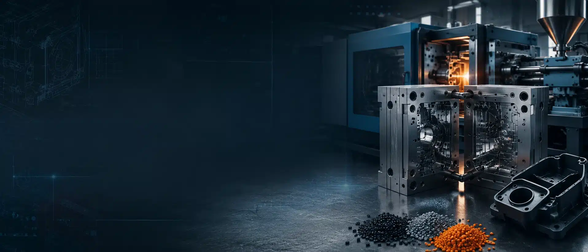
Plastic Molding Part Design
Table of Contents
What is a product “Designed for Production”?
To satisfy the requirements of designing for production, a product must be functionally sound, it must have sales appeal, and it must be competitive in price.
In order for a product to be made economically by plastic mold, it must be designed so that the most appropriate materials and processes will be utilized.
An engineer cannot do an effective job of product design unless he knows or is supplied with adequate information as to how his designs will be produced.
Therefore, the principal problem of engineering for production is sound functional design plus the selection of the materials and the processes to be used so that the new product can be produced on a competitive basis.
In choosing these materials and processes, the functional designer must make many modifications and changes in his original conception.
The shape, color, size, tolerance requirements, texture, weight, and functional design itself may be affected before the ideal design is developed that is functionally sound, has sales appeal, and is economical to
produce within the required time.
Plastics offer designers the opportunity to optimize their designs by studying various design parameters including material composition and product structural geometry in order to meet different product requirements.
Many structural plastics may exhibit a low modulus of elasticity, which is, in fact, one of the key defects in their design. Plastics, in general, are commonly used for applications requiring substantial static and/or dynamic loads.
In order to address the problem of shape integrity under load, low modulus structural plastics are designed shape-wise and/or thickness-wise to take advantage of their low modulus and achieve maximum stiffness.
Plastic products of this type comprise most of the plastics produced worldwide.
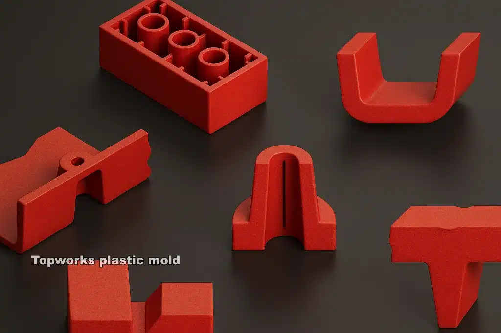
Structure Design
A reasonable and optimal molded part structure design can not only simplify plastic injection mold manufacture, reduce the cost of the mold, but also simplify its molding process to improve the good quality rate of products.
Before the design of plastic parts, a designer should learn about the function, environmental conditions, and loading conditions (including dynamic and static load), understand relations between different parts, and the effect of the assembly.
Plastic parts function should be accurate and as detailed as possible, the more comprehensive the plastic parts design is, the better the design of the plastic parts can meet the requirements.
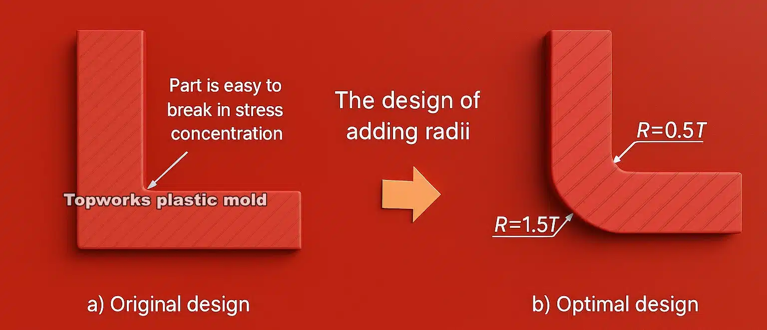
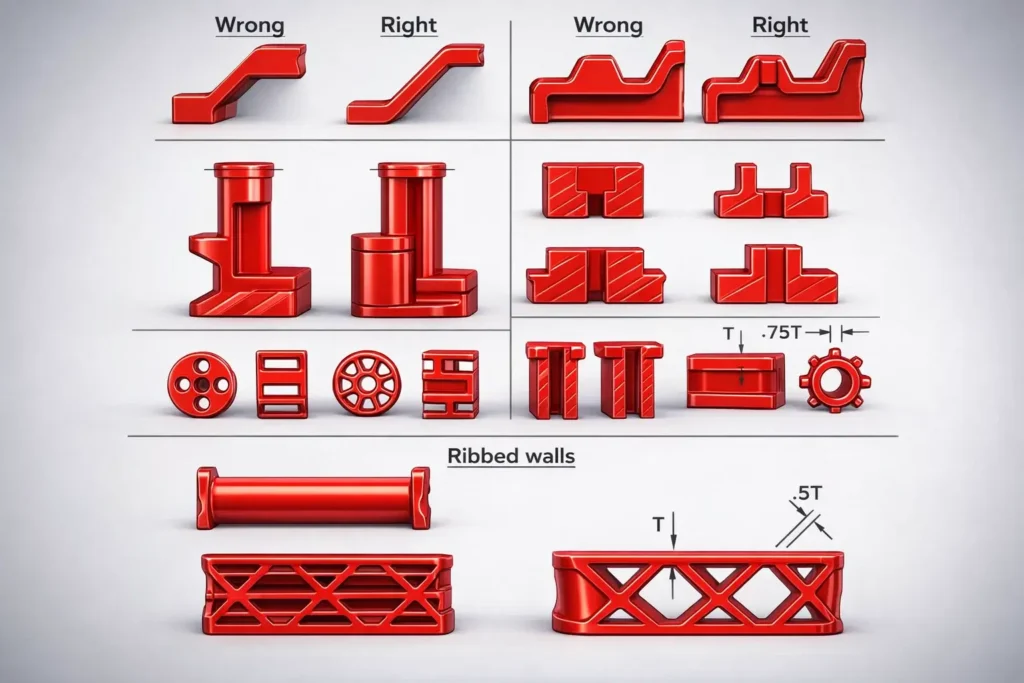
Radii
Plastic part failure can be caused by two factors: molded-in notches and sharp internal corners. In many cases, these problems are caused by designers not providing the part with an adequate internal radius in order to avoid the problem.
Radii are often inadequately noted in drawings and their importance is not considered in high-stress areas. In reality, inner corners require a radius that is carefully selected to prevent stress to be concentrated in these critical areas.
The forces at this corner will be tripled or even quadrupled if the turn is too sharp. In that case, a radius or fillet of 0.5-0.6 times the thickness of the wall should be incorporated at these points. As such, these parts will be able to reduce stress on sharp, non-radiused corners of pieces when compared to sections that have been radiused.

In addition, materials with low elongation are highly susceptible to cracking under external and internal forces, for instance when a screen is assembled and the outer diameter of the screen expands due to a complex alignment process.
In addition, the outside corners of some parts must have precise radii on them so that the square-cornered shaft can be fitted into the plastic housing.
In addition to reducing sink and stress, radii on corners enhance the material glow. Examples of these parts include pulleys and gears. In a nutshell, the smaller the radius of the section, the larger its capacity to absorb impact loads.
For example, there are designs that need an acute 90-degree corner. If your part is subjected to impact, then corners must be rounded so the energy can be absorbed and reinforced at the corners.
However, radii can negatively affect the appearance and the packaging of parts. when this is not feasible, the designer could get a material that’s impact-modified.
When the radius of the test object is increased, under test conditions, the parts are able to absorb more energy before failing, and sometimes they are able to prevent failure altogether.
A test using a large corner with rounded corners has shown that energy absorption can be increased by up to five times, and at the top, can be increased by ten times.
On the other hand, if the part contains ribs to make it stiffer, those ribs can have a negative effect on the part’s capacity to absorb energy, because the walls cannot deflect.
Proper design of the rib section, though, and use of impact-modified resin can solve the design problem in practice.
Examples of such a material are poly-carbonate which is very good at absorbing energy, and when combined with something that has a larger radius, the part will be able to absorb a lot more energy before failing.
In order to gain a better understanding of why thermoplastics behave the way they do, and why some are naturally stronger than others, it is crucial to recognize how these materials will behave in ASTM tests of their physical properties.
All plastics are subject to the same stress/strain curve, where the failure occurs close to or at the top of the curve (however the distribution of filler and reinforcements will differ).
Filled or reinforced resin exhibits a less elastic elongation than unfilled resins- about 10 percent to 15%- which indicates they will have a harder time deflecting or inflicting damage.
Therefore, they need a larger radius to decrease stress concentrations.
When examining datasheet values for short or long glass-reinforced resins, those values often come into question. According to the data, reinforced resins with greater density have an increased impact value.
In reality, the strength of the resin matrix is determined by the strength of the glass fiber within the matrix; not by the absorbing ability of the resin itself.
When the glass content is higher, the radius needs to be larger to make the part tougher.
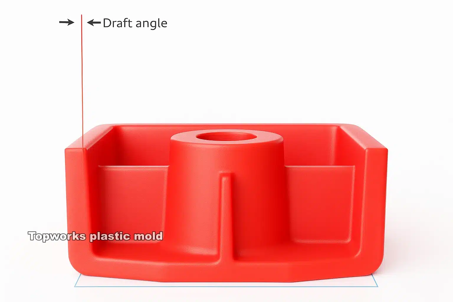
Draft Angle
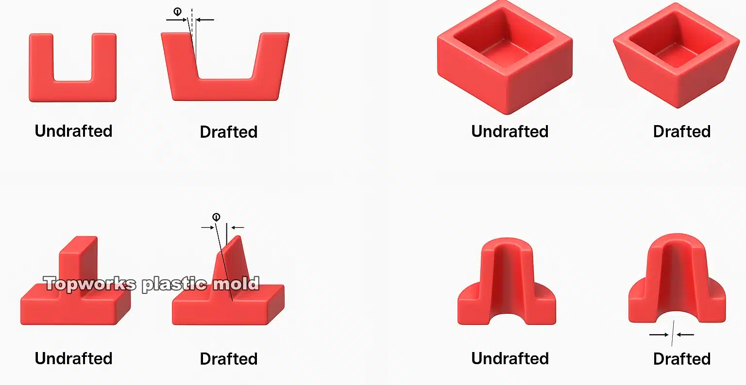
In the plastic molding industry, the draft refers to incline angle between the vertical surfaces of the molded parts and the direction in which the mold opens. Molded parts are normally ejected from molds with help from drafts.
Designers avoid significant drafts when creating products since it alters the aesthetics and reduces the volume of the final product. Plastic moldings, on the other hand, often make use of drafts in order to prevent ejection problems and overly complex tooling designs.
Specifying angles on ribs is very important. In one example, the molded part was ejected from the mold with a 2° draft angle. As for the functionality of the product, a lesser draft angle is desirable since it allows for thicker and taller ribs with more rigidity.
The part features drilled into the mold parallel to the parting line require taper to facilitate proper ejection. This draft creates a clearance once the mold begins to open, allowing the part to break free allowing the mold to open.
As a thermoplastic cools, it shrinks. And they grip cores or male forms and make ejection difficult if the proper amount of draft is not considered. An adequate amount of draft and shutoff in a mold is often sufficient to eliminate side actions and reduce tool and maintenance costs.
Low draft angles (such as xh or 1°) can cause excessive molding stickiness. A sticky part upon part ejection is more likely to occur when molds are made with mica- and/or glass-filled materials because they shrink less and have a rougher surface. Therefore, draft angles are determined by a variety of factors, including material behavior, manufacturing methods, and finish quality.
Draft angles generally range from 1 to 2° depending on the recommendations of the material supplier. It is common to apply an additional 1° of draft per 20 jams of surface roughness or texture depth to rough and textured surfaces.
For a few different surface finishes and materials, the draft angle recommended in table below increases as surface roughness increases. Materials with glass-filled or low-shrinking characteristics should have a greater draft angle, while highly flexible materials, such as soft PVC, may decrease it.
Finish / SPI / Method / Ra
Scroll →
| Finish | SPI* standard | Finishing Method | Typical surface roughness Ra (μm) |
|---|---|---|---|
| Super High Glossy | A-1 | Grade #3, 6000 Grit Diamond Buff | 0.012 to 0.025 |
| High Glossy | A-2 | Grade #6, 3000 Grit Diamond Buff | 0.025 to 0.05 |
| Normal Glossy | A-3 | Grade #15, 1200 Grit Diamond Buff | 0.05 to 0.10 |
| Fine Semi-glossy | B-1 | 600 Grit Paper | 0.05 to 0.10 |
| Medium Semi-glossy | B-2 | 400 Grit Paper | 0.10 to 0.15 |
| Normal Semi-glossy | B-3 | 320 Grit Paper | 0.28 to 0.32 |
| Fine Matte | C-1 | 600 Grit Stone | 0.35 to 0.40 |
| Medium Matte | C-2 | 400 Grit Stone | 0.45 to 0.55 |
| Normal Matte | C-3 | 320 Grit Stone | 0.63 to 0.70 |
| Satin Textured | D-1 | Dry Blast Glass Bead #11 | 0.80 to 1.00 |
| Dull Textured | D-2 | Dry Blast #240 Oxide | 1.00 to 2.80 |
| Rough Textured | D-3 | Dry Blast #24 Oxide | 3.20 to 18.0 |
| As machined | – | Finished to the machinist’s discretion | 3.20 (with visible machining marks) |
For untextured surfaces, a standard draft is recommended up to 2 degrees per side for textured surfaces, although there are exceptions. Polishing along the lines of the draw lines or using special surface treatments can help reach this goal.
In most situations, a draft of one to three degrees is recommended. As a draft increases, the ejection will become easier, but the risk will be greater that certain sections will become too heavy. When a stepped parting line is needed, the shutoff angle should be kept within 7 degrees. 5 degrees should be considered the minimum.
Wear at the shutoff will result in flashing during molding, resulting from the drag at the shutoff. This type of tooling will require more frequent maintenance if no flash will form during molding.
●
Holes
Holes
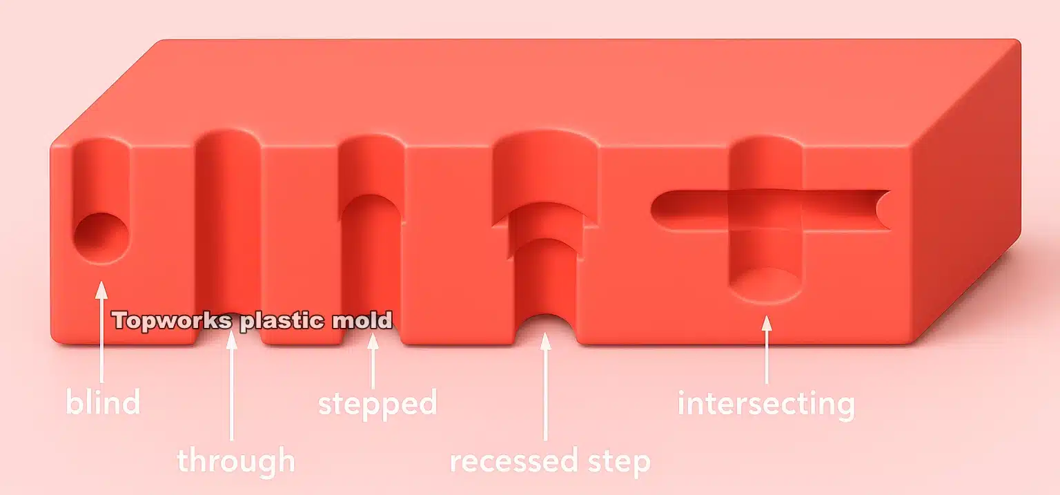
In molded parts, core pins can be used to create holes. In general, through-holes are more common than blind holes since they can support the core pin at both ends.
●
Blind Holes
Blind Holes
Molds with only one core pin are used to create blind holes. Injection-phase deflection can limit the length of the pins and, thus, the depth of the holes due to the strength of the core pin.
In general, the diameter of the blind hole should not exceed three times the depth. It is recommended that this number be reduced to two for diameters less than five millimeters.
●
Through Holes
Through Holes
Since through holes can support the cores in the opposite cavity, they can be longer. Split cores can be inserted into both halves of the mold and locked together when the mold is closed as an alternative to this.
It is possible for the core diameter for through holes to be double that of blind holes. If the cores are very long and slim, the tool design must be delicate to ensure that pressure is distributed evenly during filling to minimize deflection.
The hole must be perpendicular to the direction of the mold’s opening when using retractable pins or split tools. A step or extreme taper can be incorporated into some designs to eliminate this problem.
For more information, refer to the draft section. A polished finish should be applied to the pins in the core, and a draft should be incorporated to ease ejection.
By designing slots that direct melt flows into thicker or less critical areas, welding along these strips will be unnecessary. Even if welding is not possible due to strength or appearance criteria, weld holes can be drilled after molding to establish weld lines.
Separate two holes or one hole from the edge by at least two times the part thickness or hole diameter.
To prevent surface defects on the other side of blind holes, at least 20% of the hole diameter must correspond to the thickness of the bottom. A blind hole should not have sharp corners that will cause stress concentrations.
●
Warpage
Warpage
The molding will not deform or warp when the shrinkage is uniform throughout the part; it will only become smaller. Warpage, on the other hand, can be considered to be a distortion where the parts do not keep close to the original shape.
The part warps as a result of differential shrinkage due to residual stresses in the molded part.
The reason why shrinkage can vary is due to molecular and fiber orientations, changes in temperature in the mold, variations in packing, such as over-packing at gates and under-packing at remote locations, and variations of pressure as the material solidifies.
There are a great number of factors in play, which make it hard to achieve uniform shrinkage. These causes are explored in more detail in the information that follows.
●
Influence
Influence of unfilled and filled materials
In fiber-reinforced thermoplastics, a smaller thermal contraction and higher modulus of the reinforcing fibers inhibit shrinkage, so the fiber-reinforced material shrinks less along with the orientation of reinforcement (typically in the ow direction) as compared to shrinkage in the transverse direction.
The same is true for particle-filled thermoplastics, which shrink less than un-filled but exhibit a more isotropic structure. Warpage is generally influenced by wall thickness and molding temperatures. If the first two are not optimal for the material, the latter may warp.
Glass-reinforced materials display totally different characteristics as a result of a different orientation. A contrast in the warpage is visible between a non-reinforced and a reinforced structure.
●
Influence
Influence of cooling
When cooling the part unevenly from the core to the outer wall, as well as when cooling asymmetrically from the cavity to the outer wall, it can cause an inconsistent amount of shrinkage, which leads to warpage after ejection.
●
Influence
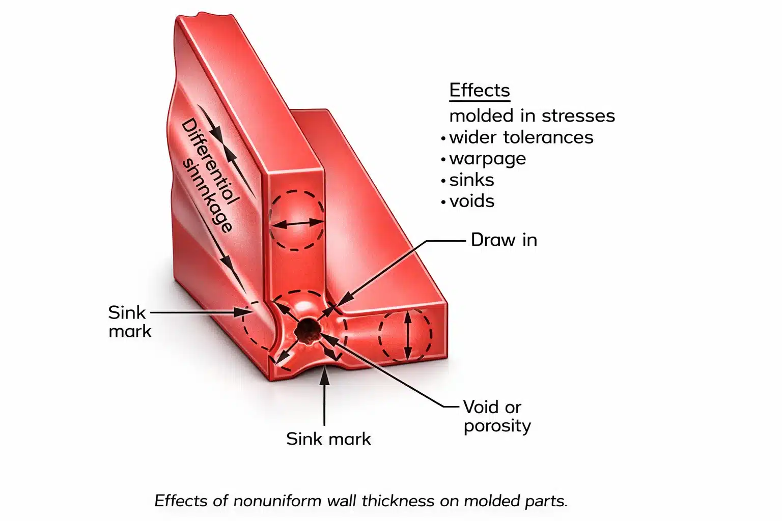
Influence of wall thickness
A large amount of shrinkage occurs where there are non-uniform wall thicknesses. A significant portion of part shrinkage is caused by varying cooling rates because of various wall thicknesses in part sections of different thicknesses.
As a result of higher volumetric shrinkage in the slow-cooling areas, there may be differential shrinkage and consequently part warping.
●
Influence
Influence of asymmetric geometry
The ribbed side of the plate will heat the material slower, and this will lead to a warpage of the part. Poor cooling of the wall on that side can cause the wall to cool too slowly, causing the material to cool too slowly resulting in warpage.
●
wall-thickness
wall-thickness
The plastic part must be strong, stiff, insulated, lightweight, durable, and able to flow smoothly.
The preferred effect is to minimize as much as possible the wall thickness of the plastic parts.
Plastic parts vary in thickness due to the nature of the material.
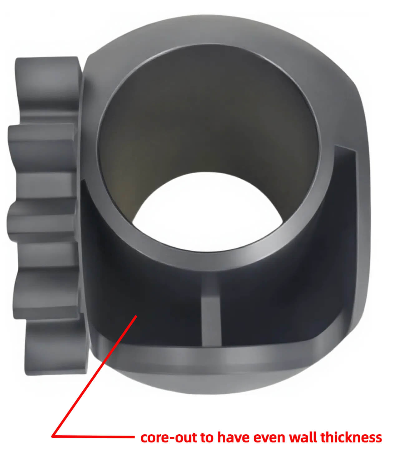
For plastic items, make sure the wall thickness is as uniform as possible. A wall thickness difference of less than 30% is acceptable. However, that difference may be alleviated by hollowing out the thick part of the plastic item.
The flow length is highly dependent on the wall thickness of the plastic part. A thicker wall will enhance the flow, whereas a thinner wall will decrease it significantly.
●
Design Principle
Design Principle
An overly thick or overly thin wall in plastic product designs can adversely affect performance. The design should take into account the structural and mechanical features of the plastic products and the mold requirements.
(1) Too thin a wall on plastic parts results in a significant amount of flow resistance, making complicated and large products impossible to fill. To ensure that the overall integrity of the plastic parts, the wall thickness should be at least .5 mm
- It meets the structural requirement for strength and rigidity;
- It is capable of withstanding vibrations and impacts when demolded;
(2)Too thick a wall wastes not just raw materials but also increases cooling time, reducing productivity and inviting defects, such as bubbles, shrinkage, holes, and warpage, as a result of the increased cooling rate.
When determining the thickness of the workpiece, the following factors should be taken into consideration:
- Keep the wall thickness as low as possible while meeting the design requirements;
- By keeping the wall thickness as uniform as possible, internal stresses and deformations are reduced.
- The component subject to fastening force must possess adequate compressive strength;
- Ensure that excessively thick parts don’t develop holes or depressions due to shrinkage.
- The thickness shall be maintained constant to avoid sudden changes
- In the case of larger parts, there is no max wall thickness requirement but a wall thickness of 6-8 mm is acceptable.
●
Nonuniform Part Thickness
Nonuniform Part Thickness
It can cause flow problems around corners since it promotes dead pressure-flow around corners in some circumstances.
When melt flows from thin sections into thick ones, it will decrease the pressure.
The thin section may be overpacked due to the fact that it is sufficiently filled. In addition to this, the thick section may be under packed.
For a component to be as uniform as possible, it should be transitioned and the thick areas should be cored out.
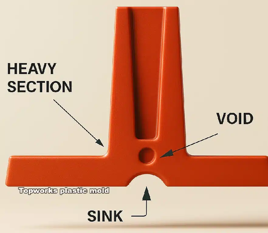
Additionally, it strengthens and reduces waste by reducing internal sinks and voids.
It is therefore important to design the walls in a uniform manner, and components should be gated into the thickest sections to ensure optimal packing and sealing.
The fact that material waste presents a significant economic burden is why it is imperative that manufacturers strive to reduce it in order to avoid future quality issues.
In the case of extra rigidity or strength, the use of ribs is recommended.
●
ribs
ribs
Reinforcing ribs play a pivotal role in the strength of a plastic part.
A number of studies have demonstrated that the ribs can effectively enhance rigidity and strength while reducing the cut surface area of a product, and they are particularly useful
for some plastic products that go through a lot of twisting, torsion, and bending.
In addition, the ribs are placed on the non-contact surfaces of the plastic product, where they also act as a channel for the flow of the material into the cavity of the plastic mold.
Filling, shrinkage, and demolding can also affect where the ribs are located.
The rib may have a length that is the same as the part or only a portion of the length of that part may increase the rigidity of that part.
If the ribs are not designed to extend along the sidewall of the product, the end of the ribs should not abruptly terminate.
Gradually reducing the height of the structure until the end is completed will reduce problems such as trapped air, short filling, and scorched marking.
For shrinkage avoidance, the root of the rib should be 0.6T, and the height should be 2T (at maximum but 3T).
The rounded corner has a radius of 0.125 and its draft angle is 0.5°1.5°.
The distance between the ribs is double the thickness of the wall. The direction of the ribs is the same as that of GATE.
The root measures about (0.50.7)T; it has a rib spacing of >4T, and the length of the ribs is L3T.
- PC, PPO T<0.6T
- PA, PE T<0.5T
- PMMA, ABS T< 0.5T
- PS T<0.6T
The importance of ribs
(1) Enhance strength and rigidity of the product without causing the excessive thickness of the wall in order to reduce weight and cost, and save plastic.
(2) It can avoid distortion due to uneven stresses caused by different wall thicknesses.
In addition, the plastic melt should also be channeled to fill the thin part of the plastic.
Ribs for Strength and Quality
Where increased stiffness is required, thin rib sections are better than large, thick rib sections. It is more effective to use multiple small ribs or a single large rib that is thin, rather than one large rib that is thick.
If ribs are thinner, molding and part problems are minimized, and added impact resistance is achieved as the molded-in stresses in these areas are reduced.
Designers should, therefore, figure out how to reduce the risk of part failure, whilst still strengthening the part, using the moment of inertia calculations.
The optimum proportions of plastic should be used in an effective design to maximize the result.
Proper rib design can also help to minimize molding problems, resulting in a faster molding cycle and reduced quality control issues.
As well as color variation, note that color variation happens in both thin and thick sections. Thicker sections will produce a more vibrant, intense color.
This is particularly evident when used transparent colors, and with certain types of resins, depending on the thickness of the section.
●
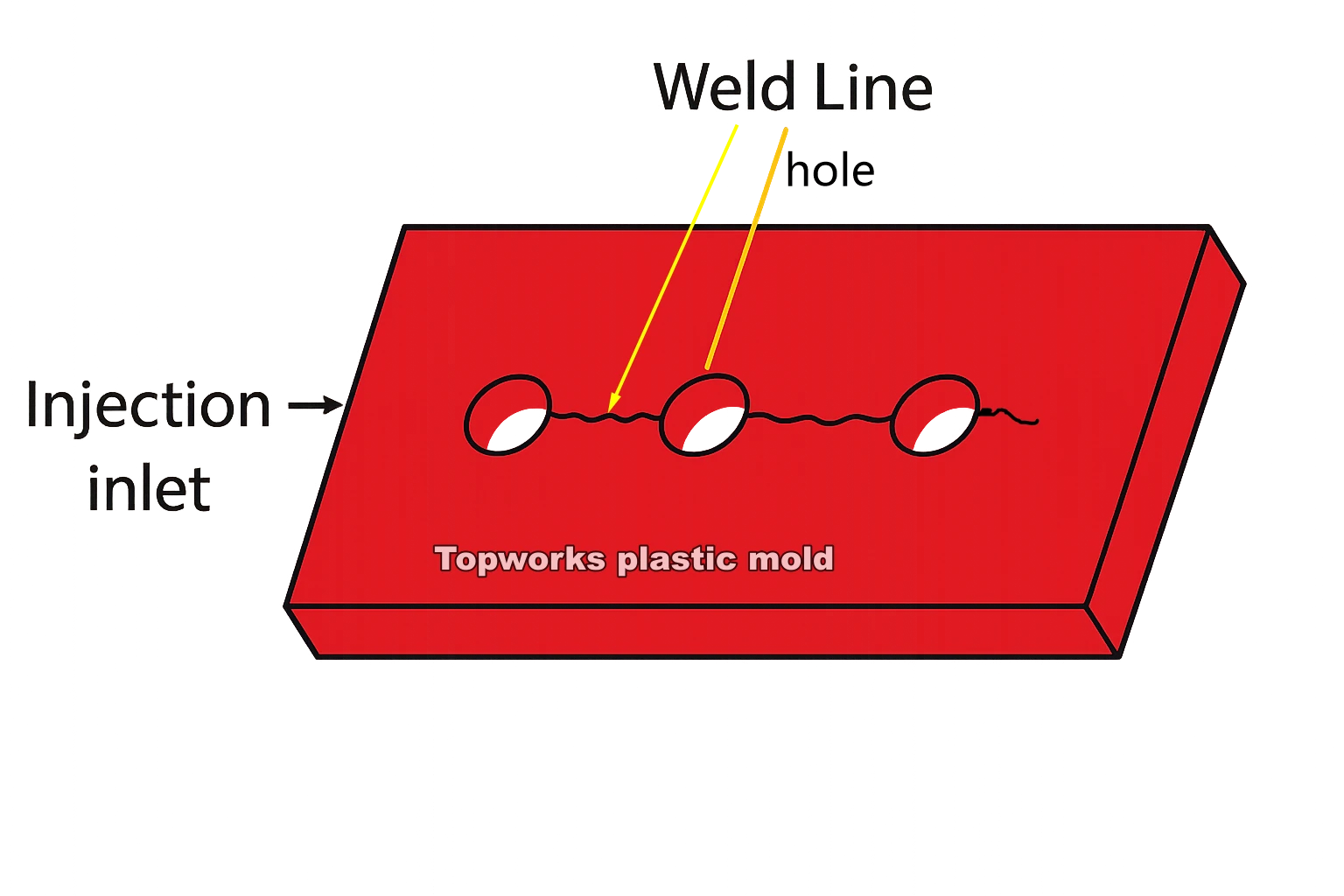
Weld-Lines
Weld-Lines
When the material is forced to flow around an obstacle, hole, boss, or cutout, or where multiple melt flows meet, a weld line will form. If the weld line is formed at a high-stress point, there may be substantial damage to the part.
As a result, designers must make a note of areas of high stress to enable the mold designer to choose the most appropriate gate location for the part.
The issue of weld-line failure is usually not recognized until after the part has failed, but by carefully planning the cavity layout and gate location, it can usually be minimized.
At these obstructions, shifting or minimizing the gate location is a valid option. Another option is multiple gating, which will change the spot where the melt fronts cross, and the weld line is formed.
The use of flow tabs, which are removed at the end of the process, is a way to strengthen weld lines at the very edge of a part.
These tabs are usually placed where the weld lines start. for the purpose of facilitating the smooth flow of melt fronts that result from melting.
However, if the mold cavity is not suitably vented, the air will stop the mold from meeting smoothly.
A buildup of air could pose a threat to the melting fronts, resulting in bubble formation, and in the event that the air is not removed quickly enough, then the melt fronts could become weakened, resulting in no re-melt.
In order to resolve this problem, extra specialized heating is often applied to welding lines to ensure the melting fronts are aligned perfectly.
There are different ways to avoid welding lines when holes are needed, especially if the welding lines occur at high-stress points.
Mark holes if required for drilling later in a secondary operation. If countersunk bind holes are necessary, retain a portion of the section thickness.
The material flow will be minimized, and the weld lines opposite the hole will be minimized as well. When blind holes are being used, there should be no less than ]/6 thicknesses on the bottom.
This is due to the fact that reinforcement materials such as glass fibers don’t flow over the weld line to interface with the opposite melt front.
Even if the external flow tab is used, reinforcement interflow is unlikely until sufficient distance has been allowed between the fronts and any obstruction.
In some parts, the welds are likely to be greatly visible.
The use of colors or reinforced materials, for example, may lead to considerable surface variation in the knit line. To increase the strength of the weld line, the resin could be melted at a higher temperature, or the mold itself could be heated.
There are usually more problems with weld lines when using amorphous resins due to their low melting temperatures in addition to their increased viscosity.
Resins with crystalline structures, which have a higher melting point, may dry out more quickly, resulting in weak weld lines.
By using flow tabs with sufficient venting, enhanced melting temperatures, localized cavity heating, and hotter mold temperatures, these weld effects can be reduced, and the strength of the joint is improved.
●
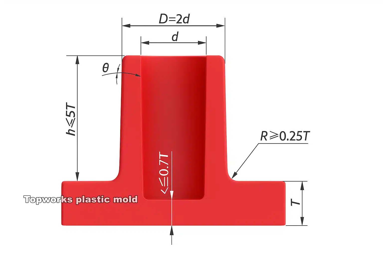
Bosses
Bosses
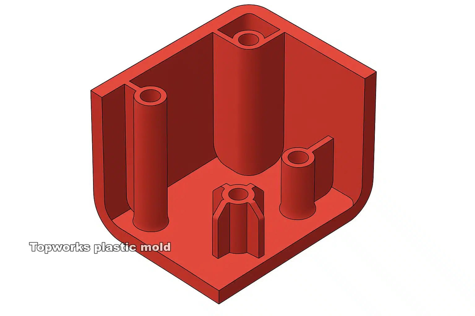
A boss is an attachment point for mating parts. As such, it is necessary to design a good mechanical attachment that does not detract from the surface or appearance of the mating part.
The latter is a problem that can be avoided if bosses are located behind the non-visible surface of a part.
A poor design of bosses or ribs will result in weld lines, voids, and sinking problems in the parts.
Regardless of whether a boss is open or BLIND, it must also have radii, and it must additionally have a uniform wall thickness across.

The final dimensions of the boss will largely be determined by the type of fastener used within it.
For extra strength, additional ribs may be added to the boss to ensure this. The final dimensions of the boss will strongly be determined by the type of fastener used within it.
Material suppliers will be able to suggest the best boss design for their own specific material. This boss design is dictated by the insert type, screw type, and holding strength necessary for the attachments.
Bosses can be designed in a number of ways.
These holes should be configured to produce surface effects while at the same time increasing the strength of the weld-line and the boss. This technique is very similar to blind holes, which allow the material to flow around and through the bottom section of the boss.
In order to complete the part’s requirements, the boss base needs to be drilled out in an additional operation. That being said, it is essential that molders design these parts with the function of assembly, molded-in appearance, and moldability in mind.
Blind holes molded in a part require rigid support from core pins, especially when the ratio of length to diameter is more than five. This is especially true with core pins that have a length to the diameter of more than five.
The pins need to be very strong and abrasion resistant in order not to bend or shift under high pressures and high speeds when the polymer is injected.
If the pin length-to-diameter given by the specification exceeds the allowed range, a stepped core pin design may be required.
Cooling will also be necessary since these types of core pins reach an extremely high temperature during the molding process.
Retractable core pins can be used when holes are present in a side wall or, alternatively, split tools may be used when the sidewall can be sloped or is tapered.
●
Threads
Threads
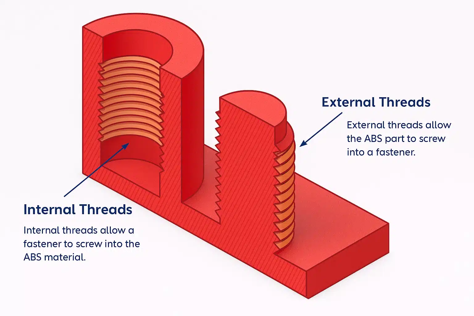
Threaded plastic parts can be created either internally or externally. Typically, the external thread is defined by locating the center of the thread as the parting line.
When this is not possible, or when the machine operates in the direction of the thread, cam-operated side cores or unscrewing devices need to be used.
On the other hand, threads running through the center of the core will require an unscrewing device or a collapsing core.
They can be removed from the mold if they are well-rounded, with minimal undercuts and depth.
If one chooses the unscrewing approach, the individual part in the mold must be index, so that while the core is being removed, it does not rotate inside the mold cavity.
If threaded components are to be stripped, threads should be shaped in a manner that is sufficient in radius in order to prevent splitting or tangling on stripping. If the thread is so shaped as to provide sufficient radii, it will not break upon stripping.
When parts need to be stripped (such as internal threaded bosses), then first the steel outside of the external diameter needs to be removed.
Consequently, when the core is stripped, the boss can expand.
The boss and parts must be appropriately supported during the stripping process so that the part will not warp. The boss must be firm enough so that it does not collapse or crack while stripping.
Threads with a diameter-to-wall thick ratio greater than or equal to 20 must have an ejection pin that is capable of disengaging the resin.
Glass-reinforced plastics can also be stripped from a mold if the part temperature is sufficiently high and the strain rate is not exceeded.
Hotter parts are able to tolerate a greater amount of material strain during the ejection process.
For example, 33% glass-reinforced nylon can be stripped from a mold kept at 100 degrees Fahrenheit if the strain is less than 1% or a mold kept at 200 degrees Fahrenheit if the strain is less than 2%.
Ensure the ideal design is selected for the optimal ejection by consulting the material supplier.
Molded-in threads need to be terminated when they reach a minimum of 0.1 inches from their end.
●
Undercuts
Undercuts
Undercuts are one of the most important features of plastic parts.
They are typically used to attach components and assemble parts, in order to reduce costs and assembly time.
Parts that feature internal and external undercuts can be produced in three basic ways – either by collapsed and pulling cores, by using split cavities, or by stripping them from the mold-like screw threads.
Depending on how deep or shallow an undercut is, as well as how much negative space is exposed underneath it, most of the stuff can be taken out of the mold.

When the return angle approaches 0.5 degrees, an undercut becomes unstrippable.
Two separate core pins can be used to create this type of internal undercut.
One end of the pin can nest inside the mating end of the pin to enhance stability, or they can slot tightly against each other to prevent flashing at the point the pins meet.
Another type of non-strippable undercut uses cores extending through the wall, or alternatively, a pin system that is offset.
Because the steel is capable of being bent, a plate or pin is used in its formation to limit the depth of the undercut. Additionally, additional knock-out ejector systems are also required for improving the undercut.
A taper of at least 2 degrees is required for the undercut when molding resins that tend to shrink during production. The sliding core will be less prone to bending and more resistant to damage when it is in contact with other metal parts.
The ability to remove undercuts in glass-reinforced resin also exists, but only if the material’s elasticity is not exceeded. The maximum undercut percentage is approximately 1% to 2% for most materials.
The use of generous release angles and radii will aid in smooth ejection, and cut stresses during release. Most parts that are used to strip undercuts are round since rectangular and closed-wall shapes cannot be stripped.
If the container is fully undercut, it will likely bend, and consequently, the parts will be locked in place.
Undercuts must be kept short around the central wall sections. and the supporting steel must be removed first in order for the wall sections to be strippable. This will allow the part to deflect as it goes into an ejection.
We conclude that the undercut section of the stripped part must be deflection-capable if ejectability is to be achieved.
●
Inserts
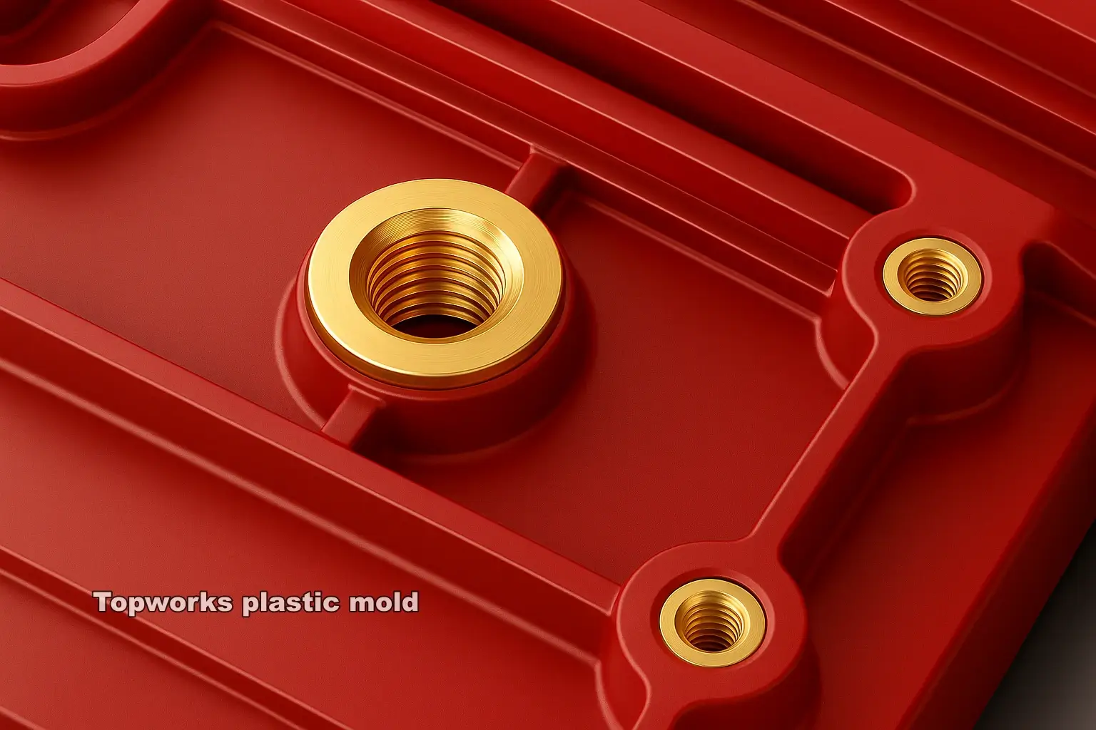
Inserts
A threaded insert is used when assembling parts.
These can be either integrated with the part or they can be mounted in a later process, either by pressing them on or by inserting them ultrasonically.
They are primarily used to increase the holding force at assembly points, reduce material creep, and access hard-to-reach areas.
Inserts are often expensive pieces of equipment and based on the parts involved and how they are installed, they can be either beneficial or detrimental.
Therefore, they are best used when necessary as with bosses and ribs.
There are alternatives that are less costly and simpler, for example, molded-in snaps or screws, which may be superior.
Inserts are used primarily for four reasons:
- For threads that are constantly stressed, or where parts have to be disassembled frequently.
- For female or male threads, the tolerance must be very high.
- In order to securely connect two loaded components- for example, a gear shaft and a pulley- permanently.
- In order to synchronize the two parts electrically.
For high shrinkage materials and parts where precise dimensional location is essential or if the risk of boss stress fractures exists, It is preferred to use ultrasonic insertion.
This is the case because the precise insert location is guaranteed, and the stress is greatly reduced for the boss.
On the other hand, the reasoning behind the use of molded-in inserts is more complex.
In spite of the fact they are cheaper and offer the advantage of being permanent, there are still several factors that must be taken into consideration before they are chosen.
Molded-in inserts can cause problems such as:
- Loading the inserts by hand will necessarily disrupt the molding cycle. While the use of robots will prolong the cycle, it will at least even it out.
- Inserts can become detached or float, causing the mold to be damaged.
- The boss stress can be reduced by degreasing and preheating.
- It is much more expensive to salvage rejected parts with inserts.
- To prevent flash on the threaded surfaces, a tight closure is necessary at the insert molding surface.
- The strength of the weld lines around the inserts needs to be taken into account.
- Boss inserts for molding must be designed to meet the existing criteria for making sure welding lines are kept as near to the edges as possible and to keep them as clear as possible.
As a result of weak coupling along the knit-line, the weld-line strength can be only about 60% of that of an unreinforced resin.
As a result, a rib at the weld line junction can strengthen the bosses at the mold line. By using multiple ribs, extra rigidity and strength can be achieved. Inserts should also be used with the following factors in mind:
Consider avoiding sharp corners, and including an undercut to enhance pullout strength.
- In order to provide a better seal to the mold cavity, the insert should protrude at least 0.6 inches through it.
- The underside of the insert should be a minimum of one-sixth of its diameter in order to strengthen the weld line.
- Toughened grades of substances, with greater elongations, will ensure that stress cracks will not develop.
- A clean, grease- and the oil-free insert is required.
- If inserts are being used with high shrinkage resins, preheating the inserts will reduce shrinkage and improve weld line strength.
- In order to ensure the correct assembly method was selected, a detailed end-use test should be carried out, which should examine the part in a range of temperatures and subject it to stress and vibration loading.
●
Tolerances
Tolerances
A high degree of accuracy in molded parts is expensive to achieve.
On small tolerances as close as -0.002 in. On large pieces, tolerances of about 土0.001 to 0.002 in. per in. are obtainable.
Tolerances closer than actually mandatory should not be specified; as specified accuracy increases, cost increases disproportionately.

Though it is difficult to generalize about design factors for injection, compression, and transfer moldings, the following design rules should be considered:
- Use sufficient draft on long thin shapes to permit their withdrawal from the mold.
- Minimize coring. When cores are used they should be easy to withdraw.
- Avoid internal and external undercuts; they make removal of parts difficult and require considerably more expensive molds.
- Provide ample fillets on inside comers, and avoid sharp external edges and comers except at the parting line of the die.
- Avoid large flat areas. Dappling or otherwise breaking up the surface is recommended.
- Keep tolerances as liberal as possible. Excessively close tolerances add to cost because of increased die costs and a high rejection rate.
- Avoid abrupt changes in wall thickness.
- Locate parting lines so that flash can be removed easily without marring surrounding areas.
- Locate holes for easy coring.
- Use ribs to achieve desired strength and stiffness. Ribs permit materials savings by reducing section thickness.
- Use inserts for threaded holes where high stresses are anticipated or where considerable wear is to be encountered. Round inserts are preferred.
Additionally, it strengthens and reduces waste by reducing internal sinks and voids.
It is therefore important to design the walls in a uniform manner, and components should be gated into the thickest sections to ensure optimal packing and sealing.
The fact that material waste presents a significant economic burden is why it is imperative that manufacturers strive to reduce it in order to avoid future quality issues.
In the case of extra rigidity or strength, the use of ribs is recommended.
