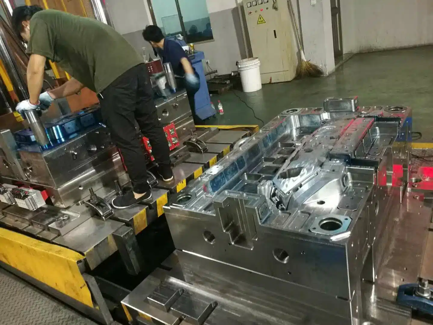

If you are sourcing PPS injection molded parts — under-hood automotive components, EV connectors, pump housings, SMT sockets — you already know the material works. The harder question is whether your molder can actually run it, and what you should be checking before you release tooling.
PPS (polyphenylene sulfide) processes at 300–340°C melt temperature with a 120–150°C mold. That is roughly double the mold temperature of nylon or ABS. It needs hardened, corrosion-resistant tooling, oil or pressurized-water temperature control, and a molder who has run it before. Get any of those wrong and you get short shots, burn marks, warped parts, or a mold that wears out in 50,000 shots.
Injection Molding Process: A Complete Overview
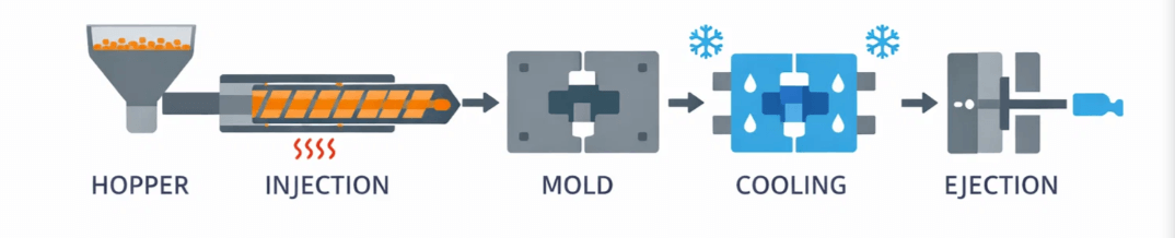
Injection molding is a high-volume manufacturing process in which molten thermoplastic resin is injected under pressure into a precision mold cavity, then cooled and ejected as a finished part. It is widely used across automotive, consumer electronics, medical devices, and packaging industries.
The six stages of injection molding
- Clamping — The two mold halves are closed and locked by the clamping unit before injection begins.
- Injection — Molten resin is injected into the mold cavity at controlled speed and pressure.
- Dwelling (holding) — Holding pressure is maintained to compensate for material shrinkage.
- Cooling — The part solidifies inside the mold; cooling time depends on wall thickness and resin.
- Mold opening — The clamping unit retracts and the mold halves separate.
- Ejection — Ejector pins push the finished part out of the cavity; the cycle repeats.
This guide gives you the actual numbers: process parameters, material properties, DFM values for wall thickness and ribs, mold steel specifications, gate sizing tables, cooling channel geometry, and ejection design. Everything you need to write a proper RFQ, review a DFM report, or challenge a supplier’s mold design.
Quick Reference: PPS Injection Molding Parameters
The complete parameter set, in one table. Detailed explanations follow below.
| Parameter | Value |
|---|---|
| PPS melting point | ~280°C |
| Continuous service temperature | 200–240°C |
| Barrel temperature (GF-filled) | 300–340°C |
| Nozzle temperature | 320–340°C |
| Mold temperature | 120–150°C (up to 160°C) |
| Drying | 150°C / 4–6 h, moisture < 0.02% |
| Injection pressure | 80–150 MPa |
| Holding pressure | 50–70% of injection pressure |
| Recommended wall thickness | 1.5–3.0 mm |
| Wall thickness variation | ≤ ±25% |
| Rib thickness | 0.4–0.6 × wall |
| Rib height | ≤ 2.5–3 × wall |
| Draft (general) | 0.5–1° |
| Draft (deep cavity) | 1–2° |
| Flow length ratio L/T | ≤ 150 |
| GF gate size adjustment | +10% vs. unfilled |
| Cooling channel diameter | 8–14 mm |
| Channel-to-cavity distance | 1.5–2 × wall thickness |
| Channel spacing | 2–3 × channel diameter |
| Vent depth for PPS | 0.02–0.03 mm |
| Mold steel (GF-PPS cavity) | H13 (44–50 HRC) or S136 (48–54 HRC) |
| Ejection safety margin | Part fully released + 1–2 mm |
| Shrinkage (GF-filled, flow direction) | 0.3–0.5% |
| UL 94 rating | V-0 (inherent) |
| Moisture absorption | < 0.05% |
| Cooling time (2 mm wall @ 130°C mold) | 25–35 s |
| Typical tooling lead time | 8–16 weeks |
What Is PPS Injection Molding? A Clear Definition
PPS injection molding is a manufacturing process that melts polyphenylene sulfide resin and injects it into a mold cavity under high pressure to create rigid, heat-resistant parts. The process follows the same fundamental steps as standard injection molding — melt, inject, cool, eject — but requires specialized equipment because PPS processes at significantly higher temperatures than commodity plastics.
PPS injection molding is a subset of thermoplastic injection molding. PPS (polyphenylene sulfide) is the material. Injection molding is the process. The output is a molded component designed for high-performance environments.
The result is a molded component that performs in environments where materials like nylon or polycarbonate would fail. PPS parts maintain their shape and strength at continuous service temperatures above 200°C (392°F), resist nearly all industrial solvents, and offer inherent flame retardancy. For a broader overview of how this manufacturing method works across materials, see our guide to plastic injection molding.
In sourcing terms, PPS sits between standard engineering plastics and metal components. It is most often specified to replace metal — reducing weight, eliminating corrosion, and consolidating multi-part assemblies into a single molding.
What Is Polyphenylene Sulfide (PPS)?
Polyphenylene sulfide is a semi-crystalline thermoplastic polymer. Its molecular backbone consists of alternating aromatic rings and sulfur atoms, which gives it exceptional thermal and chemical stability.
PPS resin is almost always reinforced with glass fibers or mineral fillers before molding. Unfilled PPS is brittle. Adding 30–40% glass fiber dramatically improves its strength, stiffness, and impact resistance. If a quotation does not state the filler content, ask — GF30 and GF40 behave differently in both the mold and the application.
Key characteristics of PPS resin include:
- Semi-crystalline structure provides dimensional stability
- High melting point of approximately 280°C (536°F)
- Inherent flame retardancy with a UL 94 V-0 rating without additives
- Broad chemical resistance across acids, bases, and organic solvents (except strong oxidizing acids such as concentrated sulfuric acid and nitric acid)
- Low moisture absorption compared to nylon (typically < 0.05%)
- Low molding shrinkage: 0.6–1.4% for unfilled grades; 0.3–0.5% in flow direction for GF-filled grades
Major PPS resin producers include Toray Industries (Torelina), Celanese (Fortron), Syensqo (Ryton), and DIC Corporation. Note: Ryton was formerly marketed under Solvay, but following Solvay’s demerger in December 2023, the Ryton PPS brand is now owned and manufactured by Syensqo. These brand names appear on technical datasheets and in supplier quotations — specifying a grade by brand and number removes ambiguity from your RFQ.
How Does PPS Injection Molding Work?
The process follows standard injection molding steps with important modifications for PPS material behavior.
Step 1 — Drying: PPS resin must be thoroughly dried before processing. Recommended drying conditions are 150°C for 4–6 hours using a dehumidifying dryer with moisture level verified below 0.02%. Alternatively, drying at 120°C for 5 hours or 150–160°C for 2–3 hours can be used depending on equipment. Moisture causes hydrolytic degradation at processing temperatures, resulting in surface defects and permanently reduced mechanical properties. A simple hot-air oven without dew point measurement is inadequate for production runs — this is worth verifying during a supplier audit. Material drying is one of several factors discussed in our overview of the plastic molding process cycle.
Step 2 — Melting: The barrel temperature is set between 300–340°C (for 40% glass-fiber-filled PPS, the range may extend to 300–350°C), significantly higher than most engineering plastics. The nozzle zone typically runs hottest at 320–340°C, while the feed zone runs lowest at 280–300°C. Precise temperature control prevents thermal degradation. For reference, pure unfilled PPS processes at 280–330°C.
Step 3 — Injection: Molten PPS is injected into a heated steel mold at injection pressures of 80–150 MPa (with holding pressure typically 50–70% of injection pressure). Mold temperatures for PPS range from 120–150°C — much higher than standard plastics — to promote proper crystallization. Some applications may use mold temperatures up to 160°C for maximum crystallinity.
Step 4 — Cooling and ejection: The part cools in the mold, crystallizes, and is ejected. Higher mold temperatures improve crystallinity, which directly improves the part’s mechanical and thermal performance. Note: Because PPS mold temperatures are 120–150°C (versus 40–80°C for most plastics), the cooling system is actually managing heat extraction from a much higher baseline, meaning cooling time is notably longer — for a 2 mm wall, approximately 25–35 seconds at 130°C mold temperature versus 8–12 seconds for the same wall in ABS at 40°C. This directly affects your per-part price.
Step 5 — Post-processing: Some PPS parts undergo annealing (controlled reheating) to relieve internal stresses and maximize crystallinity. Typical annealing conditions are approximately 204°C for 30 minutes, which improves heat deflection temperature.
Key process parameters summary for PPS injection molding:
| Parameter | Value Range |
|---|---|
| Drying temperature / time | 150°C / 4–6 h (or 120°C / 5 h) |
| Barrel temperature (GF-filled) | 300–340°C (up to 350°C) |
| Nozzle temperature | 320–340°C |
| Mold temperature | 120–150°C (up to 160°C) |
| Injection pressure | 80–150 MPa |
| Holding pressure | 50–70% of injection pressure |
| Annealing (optional) | ~204°C / 30 min |
Machine sizing considerations: Shot utilization for engineering plastics like PPS should target 30–50% of the machine’s maximum shot capacity. Cushion (residual material pad) should be approximately 5–10% of shot stroke. Clamping force is estimated as: clamping force ≈ melt pressure × projected part area × safety factor (1.1–1.3).
The specialized tooling and elevated processing temperatures mean PPS molding requires experienced processors with appropriate equipment. A molder that primarily runs commodity resins may not have high-temperature mold temperature control units on the floor.
Why Is PPS Considered a High-Performance Polymer?
PPS earns its high-performance classification because it maintains structural integrity under conditions that degrade most plastics. Heat, chemicals, flame, and electrical loads — PPS resists all of them simultaneously.
This combination of properties makes PPS a metal replacement material. Engineers specify PPS when they need the performance characteristics of metal at a fraction of the weight and often at lower per-part cost in high-volume production.
PPS bridges the gap between standard engineering plastics (like nylon 66 or PBT) and ultra-high-performance polymers (like PEEK). It offers roughly 80% of PEEK’s thermal capability at significantly lower material cost. For a deeper look at how material selection interacts with part design, our article on plastic material types and their impact on part size provides useful context.
What Are the Key Properties of PPS?
The following table summarizes the measurable properties of glass-filled PPS that matter most when specifying a part.
| Property | Typical Value (40% Glass-Filled PPS) | Why It Matters |
|---|---|---|
| Continuous use temperature | 200–240°C (392–464°F) | Survives under-hood automotive and industrial heat |
| Melting point | ~280°C (536°F) | Enables lead-free soldering compatibility |
| Tensile strength | 130–185 MPa | Structural part capability |
| Flexural modulus | 11,000–14,000 MPa | High stiffness for precision components |
| Flexural strength | ~250–300 MPa | Load-bearing capability |
| Flammability rating | UL 94 V-0 | Inherent flame retardancy without additives |
| Chemical resistance | Excellent across most solvents | Survives fuel, oil, coolant, and cleaning agents |
| Moisture absorption | < 0.05% | Dimensional stability in humid environments |
| Dielectric strength | 17–23 kV/mm | Electrical insulation for connectors and housings |
| Molding shrinkage (flow direction) | 0.3–0.5% | Predictable dimensional control |
| Density (GF40) | ~1.66 g/cm³ | Lighter than metals for weight-critical applications |
These values come from published technical datasheets of major resin suppliers. Specific grades vary by manufacturer and filler system — always design against the actual grade datasheet, not generic values.
Which Industries Use PPS Injection Molding?
PPS injection molding serves industries where part failure carries serious consequences.
- Automotive: Under-hood components, fuel system parts, EV battery housings. PPS reduces vehicle weight and withstands engine heat.
- Electrical and electronics: Connectors, sockets, relay housings, circuit breakers. PPS enables miniaturization by maintaining strength at high temperatures.
- Aerospace: Structural brackets, interior fittings, ducting components. PPS meets flame, smoke, and toxicity (FST) requirements.
- Industrial: Pump impellers, valve bodies, chemical processing equipment. PPS resists corrosive chemicals that degrade metals.
- Medical devices: Sterilizable instrument housings and surgical tool components. PPS withstands autoclave sterilization cycles.
- Consumer appliances: Hair dryer internals, oven components, coffee machine parts. PPS provides flame retardancy at consumer-grade cost.
The automotive and electronics sectors account for the majority of global PPS consumption. For compliance and quality requirements specific to medical applications, see our guide on medical device injection molding and FDA compliance.
What Automotive Applications Rely on PPS?
The automotive industry is the single largest consumer of PPS resin. PPS injection molding produces parts that survive the harsh conditions inside engine compartments and increasingly within electric vehicle battery systems.
Common automotive PPS parts include thermostat housings, coolant pump impellers, fuel rail components, EGR valve bodies, EV battery module housings and connectors, and headlamp reflectors.
The shift toward electric vehicles is expanding PPS demand. EV powertrains require high-voltage connectors and battery enclosures that withstand heat, resist flame, and insulate electrically. PPS satisfies all three requirements simultaneously. For a broader look at how injection molding serves this sector, our article on injection molding for the automotive industry covers key applications and design considerations. The Society of Plastics Engineers also provides technical resources on engineering plastics in automotive applications.
How Is PPS Used in Electronics and Electrical Components?
PPS injection molding enables miniature, high-precision electrical components that must function reliably at elevated temperatures.
PPS maintains dimensional stability during reflow soldering — the process used to mount components on circuit boards. Many plastics warp or degrade at soldering temperatures. PPS does not.
Typical electronic applications include surface-mount technology (SMT) connectors, coil bobbins, switch housings, and LED reflectors. The material’s low outgassing properties also make it suitable for sensitive optical and electronic assemblies. Our coverage of injection molding in electronics explores how high-performance polymers are enabling next-generation component designs.
How Does PPS Compare to Other Engineering Plastics?
If you are deciding between PPS and a cheaper alternative, this comparison frames the trade-off.
| Property | PPS (GF40) | Nylon 66 (GF33) | PBT (GF30) | PEEK (GF30) |
|---|---|---|---|---|
| Max continuous temp | 200–240°C | 120–150°C | 140–155°C | 250°C |
| Chemical resistance | Excellent | Moderate | Good | Excellent |
| Moisture absorption | Very low (< 0.05%) | High (~2.5%) | Low (~0.1%) | Very low |
| Flame rating (UL 94) | V-0 inherent | V-2 (needs FR additive) | V-0 (with FR additive) | V-0 inherent |
| Relative material cost | Medium-high | Low | Low-medium | Very high |
| Metal replacement potential | High | Moderate | Moderate | Very high |
| Mold temperature required | 120–150°C | 60–90°C | 60–80°C | 170–200°C |
| Drying sensitivity | Moderate | High | Moderate | Moderate |
Selection rule of thumb: choose PPS when standard engineering plastics fall short on heat, chemical exposure, or moisture stability, but PEEK exceeds the budget. If your part sees continuous service below 150°C with no aggressive chemical contact, PBT or GF nylon will almost always be cheaper to tool and cheaper to run.
What Are the Advantages of PPS Injection Molding?
- Metal replacement reduces component weight and often lowers per-part cost in volume production
- Chemical resistance eliminates corrosion concerns in harsh operating environments
- Dimensional precision enables tight tolerances in complex geometries
- Inherent flame retardancy simplifies regulatory compliance (UL, FAR, EN standards)
- Low moisture absorption prevents swelling and warpage in humid or wet conditions
- Design freedom allows consolidation of multiple metal parts into a single molded component, reducing assembly steps
- Excellent creep and fatigue resistance for long-term structural applications
- Low molding shrinkage (0.3–0.5% for GF-filled) enables predictable dimensional control
What Are the Limitations of PPS?
Know these before you commit to tooling.
- Higher material cost than commodity and standard engineering plastics like nylon and PBT
- Brittleness in unfilled grades limits use without glass fiber or mineral reinforcement
- Processing complexity requires specialized equipment, higher mold temperatures (120–150°C versus 40–80°C for standard plastics), and experienced molders
- Weld line sensitivity can reduce mechanical strength in complex parts with multiple gate locations
- Limited color options — PPS is naturally dark brown or black and is difficult to pigment in light colors
- Longer cycle times due to elevated mold temperatures — cooling takes notably longer than commodity plastics, which raises per-part cost
- Mold tooling cost is higher because PPS requires hardened, corrosion-resistant mold steels (see Mold Tooling section below)
PPS Mold Design and DFM Guidelines
Designing parts for PPS injection molding follows many of the same DFM (Design for Manufacturability) principles as other engineering plastics, but certain parameters require adjustment for PPS’s semi-crystalline behavior, high mold temperatures, and glass-fiber reinforcement. The following values are what you should see reflected in a supplier’s DFM report. For foundational DFM principles that apply across materials, our article on Design for Manufacturability in injection molding is a useful starting point.
Wall Thickness
PPS (glass-fiber reinforced) recommended wall thickness: 1.5–3.0 mm.
As a general rule across engineering plastics, wall thickness typically falls within 0.8–3.0 mm. For PPS parts specifically, maintaining uniform wall thickness is critical because the material’s semi-crystalline nature causes differential shrinkage where thickness varies. Wall thickness variation within the same part should be controlled within ±25% of the nominal thickness.
Draft Angles
| Surface Type | Recommended Draft |
|---|---|
| General exterior surfaces | 0.5–1° |
| Deep cavity interior surfaces | 1–2° |
| High-gloss / mirror-finish surfaces | 0.25–0.5° (coordinate with ejection) |
| Textured / etched surfaces | 1–3° (deeper texture requires more draft) |
| Rib sidewalls | 0.5–1.5° |
| Boss exterior | 0.5–1.5° |
| Boss internal bore | ~0.5° |
For PPS with glass fiber reinforcement, err toward the higher end of draft ranges because GF-filled melts solidify rapidly in the mold, increasing ejection forces. For a visual explanation of how draft angles work in practice, see our reference on draft angle and wall thickness.
Rib Design
| Parameter | Recommended Value |
|---|---|
| Rib thickness | 0.4–0.6 × base wall thickness (commonly 50–60%) |
| Rib height | ≤ 2.5–3 × base wall thickness |
| Rib spacing | ≥ 2 × wall thickness |
| Rib base fillet radius | R ≈ 0.25–0.4 × wall thickness |
| Rib draft | 0.5–1.5° |
Keeping rib thickness at 50–60% of the base wall prevents sink marks on the opposite surface. For PPS parts, maintaining this ratio is especially important because the rapid crystallization of PPS makes sink marks more pronounced.
Boss Design
| Parameter | Recommended Value |
|---|---|
| Boss outer wall thickness | 0.4–0.6 × surrounding wall thickness |
| Boss base wall thickness | 0.7–0.9 × nominal wall thickness |
| Boss base fillet radius | R ≈ 0.25 × wall thickness |
| Bore depth | ≤ 2.5–3 × bore diameter |
| Draft (outer) | 0.5–1.5° |
| Draft (internal bore) | ~0.5° |
For a full treatment of boss geometry, see our complete guide to designing bosses for injection molding.
Fillet Radii (Stress Control)
Internal fillet radius: R ≥ 0.25–0.5 × wall thickness. For PPS parts, particularly snap-fit features and areas subject to impact loading, use the upper end of this range. Sharp internal corners create stress concentrations that can lead to brittle fracture in glass-filled PPS.
Insert Molding / Overmolding
When molding PPS over metal inserts:
- Plastic coverage in general direction: ≥ 0.6–0.8 mm
- Plastic coverage in primary load direction: ≥ 1.0 mm
- Overmold thickness for sealing / grip features: ≥ 0.8–1.0 mm
Flow Length Considerations
The flow-length-to-thickness ratio (L/T) for PPS should generally be controlled at L/T ≤ 150. For example, with 1.5 mm wall thickness, the maximum recommended flow length is approximately 225 mm. If flow length exceeds this guideline, consider adding auxiliary gates or locally increasing wall thickness to prevent short shots.
Dimensional Tolerances
General PPS part tolerances: approximately ±0.05 to ±0.25 mm depending on dimensional range, part geometry, and tolerance grade (commercial vs. fine). Glass-fiber-filled PPS offers lower shrinkage (0.3–0.5% flow direction) than unfilled grades, making tighter tolerances achievable.
PPS Mold Tooling: Steel Selection and Specifications
PPS’s high processing temperature (mold at 120–150°C, melt at 300–340°C), glass-fiber abrasiveness, and the potential for corrosive off-gassing place demanding requirements on mold steel selection. This is the single most common place where a low-cost PPS quotation hides future problems.
Recommended Mold Steels for PPS
| Steel | Type | Typical Hardness (HRC) | When to Use for PPS |
|---|---|---|---|
| P20 (1.2311) | Pre-hardened | ≈ 28–32 | Low-volume prototype molds; not recommended for production PPS due to limited wear and corrosion resistance |
| 2738 (P20+Ni) | Pre-hardened (thick section) | ≈ 30–36 | Large mold bases where uniform hardness across thick cross-sections is needed |
| S136 (stainless) | Martensitic stainless | 48–54 (heat-treated), commonly 48–52 | Preferred for PPS cavity steel — excellent corrosion resistance against sulfur-containing off-gas, high polishability for optical/appearance parts |
| NAK80 | Age-hardened | 37–43, commonly 38–42 | High-gloss PPS parts requiring mirror finish and good weld repairability |
| H13 / 2344 | Hot-work tool steel | 44–50 (heat-treated) | Highly recommended for PPS with glass fiber — superior wear resistance against abrasive GF-filled melts, excellent hot hardness for sustained high mold temperatures |
What to specify in your RFQ: for glass-fiber-reinforced PPS (which represents the majority of PPS applications), cavity and core inserts should be H13 or S136 at 48+ HRC. The combination of high mold temperature, glass fiber abrasion, and potential sulfur off-gassing makes standard P20 insufficiently durable for production volumes. If a quotation lists P20 cavity steel for a GF-PPS production tool, question it. For reference on how steel selection relates to overall mold structure, see our overview of mould steel selection.
For PPS molds, the benchmark mold temperature is 140–150°C. Mold materials should be selected based on this operating temperature, using suitable alloy steels with hardness of HRC 48–65 and, where needed, surface plating or coating for additional protection.
Mold Manufacturing Tolerances
| Tolerance Class | Typical Range | Application |
|---|---|---|
| General cavity dimensions | ±0.05 to ±0.25 mm | Standard features |
| Precision inserts / critical fits | ±0.01 to ±0.05 mm | Tight-tolerance mating surfaces |
| Ejector pin holes, guide fits | ±0.02 mm | Positional accuracy |
Venting for PPS Molds
PPS requires careful vent design because inadequate venting causes burn marks, short shots, and trapped gas — issues amplified by the high mold temperature and rapid crystallization of PPS.
| Vent Parameter | Recommended Value |
|---|---|
| Vent depth (cavity clearance) | 0.02–0.05 mm (adjust with material viscosity — PPS has relatively low viscosity, so use the shallower end: 0.02–0.03 mm) |
| Vent width | 3–12 mm |
| Vent land width (at cavity edge) | ~1.5 mm typical; perimeter vents 3.2–6.4 mm |
| Vent locations | Opposite side from gate, flow end, runner ends, cold slug well ends, thin-wall convergence zones |
Important for PPS: Because PPS has lower melt viscosity than many engineering plastics, vent depth should be at the shallower end of the range (0.02–0.03 mm) to prevent flash while still allowing adequate gas escape.
Gate Design for PPS Injection Molding
Gate design significantly impacts the quality of PPS injection-molded parts. Glass-fiber orientation at the gate affects mechanical properties, and PPS’s rapid crystallization means gate freeze-off timing is critical for adequate packing. For background on gating systems in general, see our article on sprues, runners and gates of plastic molds.
General Gate Design Principles
- Gate cross-sectional area: typically 3%–9% of the runner cross-sectional area
- Gate land length (L): 0.5–2.0 mm, as short as possible while maintaining structural integrity
- Gate height/thickness (h): 0.5–0.75 × local part wall thickness as a starting point
Glass-Fiber Reinforced PPS: Gate Sizing Adjustment
For GF-reinforced PPS, gate cross-sectional area should be approximately 10% larger than for unreinforced grades. This reduces excessive shear at the gate which can break glass fibers, degrade mechanical properties, and cause surface defects.
Gate Type Selection for PPS
| Gate Type | Typical Dimensions | Best For |
|---|---|---|
| Side gate (edge gate) | h: 0.5–2.0 mm; b: 1.5–5 mm; L: 0.5–2.0 mm | General-purpose PPS parts, easy to control |
| Pin gate (point gate) | d: 0.8–2.0 mm (for PPS, use 1.2–2.0 mm due to higher viscosity sensitivity) | Multi-cavity molds, auto-degating |
| Submarine gate (tunnel gate) | d: 0.8–2.2 mm; angle: 30°–60° (commonly 35°–45°) | Auto-shearing for appearance-critical PPS parts |
| Fan gate | h: 0.5–1.5 mm; B: up to 10–30 mm; L: 0.7–2 mm | Thin-wall, wide PPS parts; improves front-edge uniformity |
| Diaphragm / ring gate | h: 0.3–0.8 mm | Cylindrical or circular PPS parts requiring concentric shrinkage |
| Direct gate (sprue gate) | d: 3–6 mm with R 0.5–1.5 mm transition | Thick-walled large PPS parts |
Side Gate Sizing Reference (Including PPS with GF)
| Part Wall Thickness T (mm) | Side Gate Depth h (mm) | Side Gate Width b (mm) | Pin Gate Diameter d (mm) | Gate Land Length l (mm) |
|---|---|---|---|---|
| < 0.8 | ≈ 0.5 | ≈ 1.0 | 0.8–1.3 | 1.0 |
| 0.8–1.5 | 0.6–0.8 | 1.0–1.5 | 0.8–1.5 | 1.0–1.2 |
| 1.5–2.5 | 0.8–1.2 | 1.5–2.5 | 1.0–1.8 | 1.0–1.5 |
| 2.5–4.0 | 1.2–2.0 | 2.5–4.0 | 1.5–2.2 | 1.2–1.8 |
| > 4.0 | 2.0+ | 4.0+ | 2.0–2.8 | 1.5–2.0 |
For GF-filled PPS, increase all cross-sectional dimensions by approximately 10%.
Gate Land Length Guidance
- Thin-wall, high-speed PPS parts: short land (0.5–1.0 mm)
- Thick-wall, lower-speed PPS parts: 1.0–1.5 mm or longer, depending on shear and seal-off requirements
Runner System for PPS
| Parameter | Recommended Value |
|---|---|
| Main runner (sprue) diameter | 4–8 mm (medium/small parts); 6–10 mm (large parts) |
| Branch runner diameter | Slightly smaller than main runner; 4–7 mm common |
| Runner cross-section shape | Full round (preferred) or trapezoidal |
| Cold slug well volume | ≥ 1–2× the connected runner cross-sectional volume |
| Cold slug well locations | Main runner base, runner corners, gate entry points |
Critical principle: No section of the runner should freeze before the gate. The gate must always be the first point to freeze off, ensuring proper packing of the cavity.
Multi-Cavity Runner Balancing (Cold Runner)
For multi-cavity PPS molds, geometric runner balance (equal runner length to each cavity) is the first priority. Fine-tuning involves slightly increasing the runner diameter for distant cavities and slightly decreasing it for cavities closest to the sprue. Short-shot balancing trials (filling to approximately 90–95% volume) can verify uniformity across cavities — ask your molder for short-shot samples during T1 review.
Material-Specific Gate Notes for PPS
PPS has relatively low melt viscosity compared to many engineering plastics. This means:
- Gate can be slightly smaller than for high-viscosity materials like PC or PMMA
- But GF-filled PPS requires larger gates to reduce fiber breakage
- Net effect: use standard sizing from the table above, then add the 10% GF factor
For appearance-sensitive PPS parts, fan gates or diaphragm gates are preferred to minimize visible gate vestiges and reduce weld-line visibility.
Cooling System Design for PPS Molds
Cooling system design for PPS molds is uniquely challenging because the mold operates at 120–150°C — much higher than the 40–80°C typical of standard engineering plastics. In PPS molds, the “cooling” system is actually a temperature management system: it must maintain the mold at a consistently elevated temperature to promote crystallization while extracting excess heat to maintain cycle time. For a broader look at how cooling affects overall cycle time and part quality across materials, see our dedicated article on injection mold cooling. The Plastics Technology injection molding resource center also offers authoritative technical references on cooling system design.
Cooling Channel Geometry
| Part Wall Thickness T (mm) | Channel Diameter d (mm) | Channel-to-Cavity Distance a (mm) | Channel Spacing s (mm) |
|---|---|---|---|
| 1–2 | 6–8 | 10–15 | 30–40 |
| 2–4 | 8–10 | 15–20 | 40–60 |
| 4–6 | 10–12 | 18–25 | 50–70 |
| > 6 | 12–14 | 20–30 | 60–80 |
Quick rules: Channel-to-cavity distance a ≈ 1.5–2.0 × wall thickness (typically 15–20 mm). Channel spacing s ≈ 2–3 × channel diameter (typically 40–60 mm).
Minimum Clearance Distances
| Clearance | Minimum Distance |
|---|---|
| Channel to ejector pin / sleeve holes | ≥ 5 mm |
| Channel to mold edge | ≥ 8–10 mm (prevents cracking/leaking) |
| Channel to guide pins, screw holes | ≥ 3–5 mm |
| Coolant connector face to mold edge | ≥ ~26 mm (based on standard fitting dimensions) |
Flow and Temperature Parameters
| Parameter | Recommended Value |
|---|---|
| Flow rate per circuit | 15–30 L/min (range: 10–60 L/min) |
| Flow velocity | ≥ 0.8–1.0 m/s (ensure Reynolds number Re ≥ 10,000 for turbulent flow) |
| Inlet-outlet temperature difference ΔT | 2–4°C (maximum 5°C; larger ΔT causes uneven cooling/warpage) |
| Coolant temperature setting | Mold temperature minus 5–10°C |
PPS-Specific Cooling Considerations
For PPS at 120–150°C mold temperature, the cooling medium is typically oil or pressurized hot water (not standard chilled water). The temperature control unit must be capable of maintaining stable output at these elevated temperatures. Confirm your molder has high-temperature TCUs available for your tool — this is a common equipment gap.
Cooling time estimation: Cooling time is roughly proportional to the square of wall thickness (t_cool ∝ h²). For PPS:
- A 2 mm wall at 130°C mold temperature: approximately 25–35 seconds
- A 3 mm wall: approximately 25–35 seconds (material-dependent)
- Cooling typically accounts for 50–70% of total cycle time
Cooling channel forms:
| Type | Application |
|---|---|
| Straight-through channels | First choice for simplicity; standard drilled holes |
| Baffles / bubblers | Deep cavities, long cores, cylindrical features |
| Fountain / well circuits | Core center cooling |
| Conformal cooling (3D printed) | Complex geometries; can reduce hotspot temperatures by ~50% and part warpage significantly |
For PPS parts with critical dimensional stability requirements, conformal cooling channels (produced via additive manufacturing) can dramatically improve temperature uniformity across the part surface compared to conventional straight-drilled channels.
Ejection System Design for PPS Parts
PPS’s rapid crystallization and high mold temperature create specific ejection challenges. Parts tend to grip the core tightly as the semi-crystalline structure develops during cooling.
Ejection Methods
| Method | Best Application |
|---|---|
| Ejector pins | Most ribs, boss backs, localized features |
| Ejector sleeves / tubes | Around bosses, shaft-like features |
| Stripper plates | Large-area thin-wall parts, appearance-sensitive surfaces |
| Air ejection | Thin-walled parts where pin marks are unacceptable |
Ejection Design Parameters
| Parameter | Guideline |
|---|---|
| Ejection stroke | Full part release from core + 1–2 mm additional safety margin |
| Ejector pin slenderness ratio | Control length-to-diameter ratio; excessively slender pins require guided support or diameter increase |
| Pin placement | Prioritize rib backs, non-appearance surfaces, reinforced areas; distribute symmetrically |
| Clearance from cooling channels and screws | ≥ 3–5 mm |
PPS-Specific Ejection Notes
- For PPS parts, prefer more smaller-diameter pins over fewer large pins to distribute ejection force evenly — PPS’s brittleness in thin sections makes concentrated ejection force risky.
- Large flat PPS parts should prioritize stripper plate ejection to minimize ejection marks and prevent warpage.
- Ejection force distribution should be as symmetric as possible; avoid configurations where 2–3 large pins on one side must support the entire part.
How to Evaluate a PPS Injection Molding Supplier
Most molders can quote PPS. Fewer can run it consistently. Use these checks before awarding tooling.
Equipment Verification
- High-temperature mold temperature control units. Ask how many oil or pressurized-water TCUs capable of 150°C+ they have, and whether one will be dedicated to your tool. Standard water chillers cannot run PPS.
- Dehumidifying dryers with dew point monitoring. Hot-air ovens are not acceptable for production PPS. Ask to see the dryer specification and the moisture verification record.
- Machine barrel capability. Confirm the press can hold 340°C stably and that screw and barrel are suitable for abrasive glass-filled resins (bimetallic or nitrided).
Tooling Quotation Review
| Check | What Good Looks Like | Red Flag |
|---|---|---|
| Cavity/core steel | H13 or S136 at 48+ HRC, hardness stated | P20 for a production GF-PPS tool, or steel grade unstated |
| Cooling design | Circuit layout drawing provided; channel-to-cavity distance and ΔT specified | “Standard cooling” with no layout |
| Gate type and location | Specified with reasoning; weld line locations identified | Gate position left to the toolmaker with no DFM comment |
| Venting | Vent depth stated at 0.02–0.03 mm | Not mentioned |
| Mold life guarantee | Stated shot count matched to steel hardness | High shot guarantee on soft steel |
| Mold flow analysis | Offered or included for complex parts | Declined or charged as a surprise extra |
Sampling and Qualification
- Request short-shot samples at T1 to verify fill balance across cavities.
- Request a full dimensional report against your drawing, not a spot check.
- Ask for the actual process sheet used at sampling — barrel zones, mold temperature, injection and holding pressure, cycle time. This should match the ranges in this article.
- For structural parts, request mechanical testing on molded samples rather than relying on resin datasheet values; weld lines and fiber orientation reduce real part strength.
Our guide on choosing the right injection molding manufacturer in China covers the broader supplier evaluation process, including audits and quality systems.
What Does PPS Injection Molding Cost?
PPS resin costs more per kilogram than nylon, PBT, or polypropylene. Glass-filled PPS compounds generally range from $5–$15 per kilogram depending on grade, filler content, supplier region, and order volume, though prices fluctuate with market conditions. Specialty compounds and small-volume orders command the higher end of this range; large-volume procurement from Asian suppliers may fall toward the lower end.
Tooling costs are higher than typical injection molding projects because PPS molds require hardened, corrosion-resistant steels (H13, S136 at 48+ HRC) and high-temperature-capable cooling systems with oil or pressurized hot-water temperature control. These requirements can increase upfront tooling investment by 15–30% compared to molds for commodity plastics.
Per-part cost is also affected by cycle time. Because PPS cooling runs 25–35 seconds for a 2 mm wall versus 8–12 seconds for ABS, machine hours per thousand parts are meaningfully higher. Factor this into volume pricing negotiations rather than comparing material cost alone. For a detailed breakdown of what drives mold costs, our comprehensive guide on mastering injection molding costs is recommended reading. The Society of Plastics Engineers Injection Molding Division also publishes industry benchmarks on tooling cost factors.
Against those costs, PPS often reduces total program cost by consolidating multiple components into one molded piece, eliminating secondary operations like painting or coating, and extending part service life in the field.
Is PPS Injection Molding Sustainable?
PPS is a thermoplastic, which means it can technically be remelted and reprocessed. In practice, recycling glass-filled PPS at commercial scale remains limited due to fiber degradation during reprocessing. PPS production scrap can typically be reground and reused up to approximately three times before significant property degradation occurs.
Some manufacturers regrind production scrap and blend it back into virgin material at controlled ratios. If your application has critical mechanical requirements, specify virgin-only material in your purchase agreement and state the maximum permitted regrind percentage. End-of-life recycling infrastructure for PPS is still developing; both mechanical recycling (grinding/shredding) and chemical recycling (depolymerization) methods exist but are not yet widespread.
From a lifecycle standpoint, the strongest sustainability argument for PPS is durability: parts last longer, fail less often, and reduce waste from premature replacement. Weight reduction in automotive and aerospace applications also contributes to fuel efficiency and lower emissions over the product’s service life. Our article on sustainable practices in injection molding explores how manufacturers can reduce material waste and energy use across the production process.
Frequently Asked Questions
What does PPS stand for in injection molding?
PPS stands for polyphenylene sulfide. It is a semi-crystalline engineering thermoplastic known for exceptional heat resistance, chemical resistance, and dimensional stability. PPS is almost always used with glass fiber or mineral filler reinforcement to overcome the brittleness of the unfilled resin.
Can PPS replace metal in structural applications?
Yes, PPS frequently replaces aluminum, zinc, and steel in structural and semi-structural applications. The replacement works best when the design is optimized for plastic — using ribs (0.4–0.6 × wall thickness), bosses, and variable wall thickness that injection molding allows but metal fabrication does not.
What temperature can PPS withstand?
Glass-filled PPS grades can operate continuously at 200–240°C (392–464°F). Short-term peak exposure can exceed 260°C. This makes PPS suitable for under-hood automotive environments, industrial equipment, and reflow soldering processes in electronics manufacturing.
Is PPS FDA approved for food contact?
Certain PPS grades have received FDA compliance for food contact applications. However, compliance depends on the specific grade, filler system, and intended use. Verify compliance with the resin supplier for your specific grade before making claims or releasing a design.
How does PPS compare to PEEK?
PPS offers roughly 80% of PEEK’s thermal and mechanical performance at significantly lower material cost. PEEK outperforms PPS in continuous service temperature (250°C vs. 200–240°C) and toughness, but for many applications PPS delivers sufficient performance at a more accessible price point.
What is the typical lead time for PPS injection molded parts?
New mold fabrication typically takes 8–16 weeks. Because PPS molds require hardened steels (H13, S136) and high-temperature cooling systems, tooling lead time may trend toward the longer end compared to commodity plastic molds. Once tooling is complete, production runs follow standard injection molding timelines, often days to weeks depending on order size and molder capacity.
What is the difference between PPS and PPA in injection molding?
PPS (polyphenylene sulfide) and PPA (polyphthalamide) are both high-performance polymers, but they serve different needs. PPS offers superior chemical resistance and inherent flame retardancy. PPA provides higher mechanical strength and better toughness at elevated temperatures. The choice depends on whether the application prioritizes chemical and flame resistance (PPS) or mechanical load-bearing (PPA).
What mold steel is best for PPS injection molding?
For glass-fiber-reinforced PPS, H13 (heat-treated to 44–50 HRC) is recommended for its wear resistance against abrasive GF melts and excellent hot hardness. S136 stainless steel (48–54 HRC) is preferred for PPS applications requiring corrosion resistance against sulfur off-gassing or mirror-finish cavities. Standard P20 is generally insufficient for production PPS molds.
What mold temperature does PPS require?
PPS requires mold temperatures of 120–150°C (and up to 160°C for maximum crystallinity). This is significantly higher than nylon (60–90°C) or ABS (45–80°C), requiring oil or pressurized hot-water temperature control units rather than standard chillers.
Why do PPS parts crack during ejection?
The usual causes are insufficient draft angle on deep features, too few ejector pins concentrating force on brittle sections, sharp internal corners creating stress risers, or mold temperature dropping too low so the part over-shrinks onto the core. Check draft against the table above (use the upper end for GF grades), increase pin count rather than pin diameter, and verify fillet radii at 0.25–0.5 × wall thickness.
What causes burn marks on PPS moldings?
Almost always trapped gas from inadequate venting, made worse by PPS’s high mold temperature and fast fill. Verify vent depth at 0.02–0.03 mm at the end of fill, runner ends, and cold slug wells. Reducing injection speed in the final fill stage also helps.
Conclusion
PPS injection molding produces parts that perform where standard engineering plastics fail — above 200°C continuous service, in aggressive chemical environments, and under flame and electrical requirements that would otherwise force a metal design.
The material is not the hard part. The mold is. Steel selection, gate design, cooling circuit layout, and ejection strategy determine whether a PPS part reaches the properties on the datasheet or falls short in the field. A quotation that does not specify cavity steel hardness, cooling layout, and vent depth is not a complete quotation.
If you are sourcing PPS parts and want a second opinion on a DFM report or a tooling quotation, our engineering team reviews part drawings and advises on mold construction before you commit to tooling.

