
PPS Injection
Molding: merged
technical guide
A consolidated engineering reference for PPS material behavior, processing windows, DFM rules, mold steel, gate/runner layout, cooling, ejection, defects, grade choice, applications, and program cost.
Nobody picks PPS injection molding because they like it. PPS shows up after PA66 cracked at 180°C, or PBT swelled in coolant, or PPA missed a tolerance after thermal cycling. Get the process right and the part outlives the program. Get it wrong and you’ll fail T1 the same way every time.
This merged guide is for engineers qualifying PPS, molders quoting PPS tooling, and technical buyers who need to separate real PPS capability from generic plastic-molding claims. It combines material fundamentals, processing parameters, DFM geometry, steel selection, gate and runner design, cooling layout, ejection strategy, troubleshooting, application fit, and total program cost. The tone is intentionally technical: PPS defects are not generic molding defects, and PPS tooling is not generic engineering-plastic tooling.
§ 01 — Foundations What PPS is, and why engineers reach for it 01
Polyphenylene sulfide is a semi-crystalline engineering thermoplastic. Para-phenylene rings linked by sulfur atoms. That backbone does the heavy lifting. Aromatic rings give stiffness and thermal stability. The sulfide linkages make it self-extinguishing. Crystallinity keeps the part dimensionally honest across a wide temperature swing.
PPS sits in a useful gap. Better thermal and chemical performance than PA66, PBT, or PPA. A fraction of what PEEK or polyimide costs. One number defines its commercial appeal: no known solvents below 200°C. That’s why you see it in fuel systems. In coolant pumps. In chemical handling. Under EV battery packs, where the thermal load keeps climbing.
PPS in the performance-polymer hierarchy
The chart below plots the polymers a program engineer cares about. Two axes: continuous service temperature against resin cost. PPS lands in the upper-middle band. Most of PEEK’s heat resistance at roughly a quarter of the price.
Unfilled, glass-filled, and the grades in between
Unmodified PPS is brittle. That’s the headline weakness. It’s also why over 80% of molded PPS in the market is reinforced. The default is 40% glass fiber — the PPS-GF40 family. Glass roughly doubles heat-deflection temperature. Triples flexural modulus. Gives the part enough toughness to survive press-fit assembly and field service.
Three other variants worth knowing:
- Mineral-and-glass blends — when anisotropic fiber shrinkage warps the part beyond spec. Large flat covers. Optical brackets.
- Tribological grades — PTFE or graphite filled. For bearings, slides, seal faces where wear kills the part.
- Unfilled grades — chemical-handling, capacitor housings, anywhere a filler would tank dielectric strength or purity.
Pick the grade family from the failure mode you’re avoiding. Reinforced grades fix mechanical and thermal problems. Unfilled grades fix chemical and electrical problems. Tribological grades fix wear. Specifying GF40 for a chemical-isolation part is a classic, expensive mistake.
Core PPS properties engineers should put on the first-page brief
For specification work, the grade matters. Still, GF40 PPS has a fairly predictable property band, and these are the values worth carrying into early material selection, DFM, mold quotation, and customer technical discussion.
Table 01A · GF40 PPS property reference · Typical values used for early engineering screening
| Property | Typical value | Engineering meaning |
|---|---|---|
| Continuous use temperature | 200–240°C | Survives under-hood, hot-fluid, and industrial heat exposure. |
| Melting point | ~280°C | Supports high-temperature assembly environments, including many solder-adjacent designs. |
| Tensile strength | 130–185 MPa | GF grades can carry real structural load, not just cosmetic housings. |
| Flexural modulus | 11–14 GPa | High stiffness for precision connector, pump, and bracket geometries. |
| Flexural strength | 250–300 MPa | Useful for load-bearing ribs, arms, and brackets when weld lines are controlled. |
| Flammability | UL 94 V-0 inherent | Flame performance without relying on additive packages that can compromise properties. |
| Moisture absorption | < 0.05% | Much better dimensional stability than nylon in humid or wet service. |
| Dielectric strength | 17–23 kV/mm | Supports connectors, bobbins, sockets, and other electrical insulation applications. |
| Density, GF40 | ~1.66 g/cm³ | Major weight reduction versus aluminum, brass, and stainless replacements. |
| Chemical resistance | Excellent across fuels, oils, coolants, bases, and most solvents | The main reason PPS wins in pumps, valves, and fluid-contact parts. |
PPS is not a universal “best plastic.” It is a high-value fit when heat, chemical exposure, flame behavior, electrical insulation, or dimensional stability are real constraints. If the part only sees 120–140°C and mild chemistry, PPA or PBT may be a more honest choice.
§ 02 — The Process PPS processing parameters: the engineer’s reference02
The PPS process window is friendlier than its reputation. Three rules are non-negotiable: dry the resin, run the mold hot, and use the right steel. Break any one of the three and you’ll see defects that look like material problems. Then you burn a week chasing the wrong root cause.
The table below is the starting window for the two grades that cover most commercial PPS work. Treat it as the start of your DOE — not gospel. Every resin lot pulls these numbers a little. Every cavity geometry pulls them more. But if your first setup is outside these ranges, you have a problem before you’ve made a part.
Table 01 · Recommended processing window · Unfilled vs glass-filled PPS
| Parameter | Unfilled PPS | GF40 PPS |
|---|---|---|
| Barrel temperature | 300–325 °C | 310–340 °C |
| Mold temperature | 120–150 °C | 135–150 °C |
| Drying conditions | 150 °C / 4–6 hr (desiccant dryer, dew point ≤ −30 °C) | 150 °C / 4–6 hr (desiccant dryer, dew point ≤ −30 °C) |
| Injection speed | 40–80 mm/s | 40–80 mm/s |
| Injection pressure | 80–130 MPa | 100–150 MPa |
| Back pressure | 5–10 MPa | 5–10 MPa |
| Hold pressure | Maximum tolerable without flash | Maximum tolerable without flash |
| Shot utilization note | 30–50 % of machine max | 30–50 % of machine max |
| Shrinkage — flow direction | 0.6–1.4 % | 0.3–0.5 % |
| Shrinkage — transverse | 0.6–1.4 % | 0.8–1.2 % |
Note — Shot utilization for engineering resins is held to 30–50% of machine max. Keeps residence time short and stops thermal degradation in the barrel.
Process sequence and setup checks
The molding sequence is still melt, inject, pack, cool, eject. PPS changes the discipline around each step. Drying is verified by dryer dew point, not by oven time. Melt temperature is high enough that residence time must be controlled. The mold is hot enough that crystallinity becomes a process variable. Ejection is run after the part has released, not just after the timer says the cycle is over.
Table 01B · Setup additions · Values that are easy to miss on first PPS programs
| Item | Recommended value / rule | Why it matters |
|---|---|---|
| Nozzle temperature | 320–340°C | Prevents freeze-off and pressure spikes at the nozzle, especially on GF grades. |
| Feed-zone temperature | 280–300°C | Keeps feed stable while limiting unnecessary residence-time degradation. |
| Holding pressure | 50–70% of injection pressure, then optimize to flash limit | Maintains dimensions without overpacking low-viscosity PPS. |
| Cushion | 5–10% of shot stroke | Protects packing repeatability and exposes check-ring leakage early. |
| Shot size | 30–50% of barrel capacity | Limits residence time while keeping the machine in a controllable pressure range. |
| Clamp force estimate | Projected area × melt pressure × safety factor 1.1–1.3 | PPS flashes easily; clamp calculation must be tied to real projected area and peak pressure. |
| Annealing, optional | ~204°C / 30 min | Useful for stress relief and maximum heat-deflection stability on tight-tolerance parts. |
Why drying is non-negotiable
PPS barely absorbs moisture — under 0.05% at equilibrium. The small amount it does absorb is catastrophic in the melt. Sulfide linkages hydrolyze. Hydrogen sulfide gases off. Chain scission cuts molecular weight. Visible symptoms: splay, streaking, voids, weak weld lines. The invisible symptom is the dangerous one — reduced impact strength on a part that passed visual QC.
Use a desiccant dryer. Dew point below −30°C. Hopper dryers don’t work — they can’t move enough air at 150°C to pull water out of the granules. Audit the dryer at the throat. If the thermocouple reads 110°C, you don’t have dry resin. You have wet resin and a paperwork trail saying otherwise.
Mold temperature controls crystallinity — and therefore everything else
This is the parameter that separates molders who really run PPS from molders who say they do. Below 120°C, the skin freezes before the polymer can crystallize. You get an amorphous shell on a semi-crystalline core. The part looks fine. It passes first-article dimensional QC. Then in the field, under thermal load, it slowly crystallizes — and warps, cracks, or post-shrinks.
Above 135°C, crystallinity hits the target range (30–40%). The part is dimensionally stable. Impact matches the datasheet. The price of admission is mold heating that can actually hold 150°C across every cavity. That means hot oil — not water, not cartridge heaters. Water tops out around 130°C unless you go high-pressure. Cartridges deliver the temperature but not the uniformity.
Injection speed and the V/P transfer
PPS has unusually low melt viscosity for a high-performance polymer. That’s part of why it flashes. The instinct is to slow the fill to compensate. Wrong move. PPS wants to fill fast — or the flow front freezes mid-cavity before pack starts. Use a multi-stage velocity profile. Slow into the gate (10–20 mm/s) to kill jetting. Aggressive through the part (60–80 mm/s). Controlled slow-down into V/P.
Set first-stage pressure 200–400 psig above the peak fill pressure. Trigger V/P transfer on position — typically at 95–98% volumetric fill. Pack pressure goes to whatever the machine delivers without flashing. Hold until the gate freezes. Skip this and the part loses impact strength. It also drifts dimensionally after molding. Both are invisible until the part is already in service.
§ 03 — The Tool Mold design for PPS: what’s different03
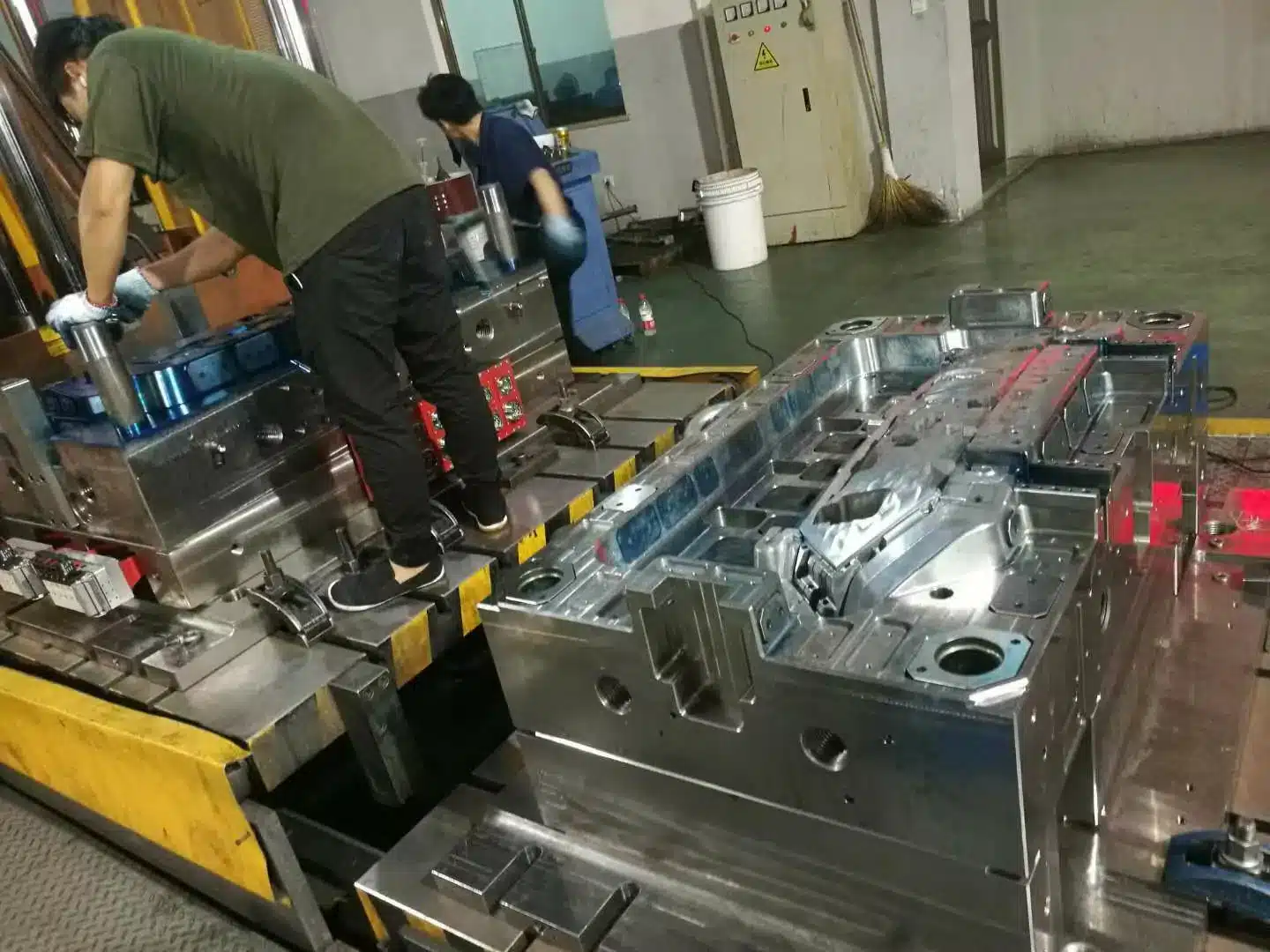
Glass-filled PPS is one of the most abrasive thermoplastics anyone runs in production. A tool that took 800,000 cycles on PA66-GF30 will show visible gate and parting-line wear inside 100,000 cycles on GF40 PPS. The usual shop response — “we’ll use H13” — is necessary. Almost never sufficient.
Tool steel selection & cavity-life economics
The table below shows typical cavity life and hardness for the five steel grades you’ll see specified on PPS tools. Hardness values are industry-standard delivery state. Always ask the supplier for the datasheet. Verify heat-treatment certification on incoming material before machining.
Table 02 · Tool steel reference · Hardness, cavity life, and application scope for GF40 PPS
| Steel grade | Hardness (HRC) | Typical cavity life (shots) | Tooling cost index | Application notes |
|---|---|---|---|---|
| P20 / 1.2311 | 28–32 (pre-hard) | 30,000 – 80,000 | 1.0× | Prototype and low-volume only. Don’t run GF40 production on it. |
| 2738 (P20+Ni) | 30–36 (pre-hard) | 50,000 – 120,000 | 1.15× | Large mold bases. Better through-hardness than P20. Still too soft for GF40 long-run. |
| NAK80 | 37–43 (pre-hard, age-hardened) | 100,000 – 200,000 | 1.3× | Welds and repairs well. Pick it where mold changes are likely. |
| H13 / 1.2344 (hardened) | 44–50 (quench + temper) | 200,000 – 300,000 | 1.4× | Standard production. Add hardened gate inserts for GF40. |
| S136 / 1.2083 (stainless) | 48–54 (quench + temper) | 250,000 – 400,000 | 1.6× | Pick this when H₂S off-gas or coolant corrosion is also on the table. |
| PM steels (M2, M390, ASP) | 58–62 | 1,000,000 + | 2.5–3.5× | Multi-year automotive programs. Match the steel bill to the lifetime part count. |
This is never “buy the hardest steel.” It’s a TCO calculation: program volume × cavity life × refurbishment cost. Under 100,000 lifetime parts, hardened H13 with replaceable gate inserts beats PM steel on cost. For multi-year auto programs in the millions, the math flips hard the other way.
Parting-line venting
Vent depth for PPS is tighter than the 0.02–0.05 mm you’d use for commodity resin. PPS’s low melt viscosity walks straight through a standard vent and flashes. Spec 0.010–0.013 mm on parting-line vents — roughly half of what you’d cut for PA66 or ABS.
vs. 0.02–0.05 mm for commodity resins
Larger vents at flow-end, weld-line zones
Perimeter land: 3.2–6.4 mm
weld-line confluence, thin-wall merge zones
Designing for 150°C mold operation
Running the mold this hot has two practical consequences. First, thermal expansion between platen and mold matters. Add insulator plates between mold and press platens. They isolate heat and protect the platen face. Second, your water (or oil) layout has to deliver tight cavity-to-cavity uniformity. ±3°C across cavities is achievable with conformal cooling on the critical cores. ±5°C is the loose limit. Past that, warp starts trending across the lot.
DFM geometry rules for PPS parts
PPS follows the same DFM logic as other injection-molded materials, but the penalty for violating the rules is higher. Semi-crystalline shrinkage, rapid skin freeze, and glass-fiber orientation all amplify wall-thickness changes, sharp corners, and weak gate strategy. Put these values into the first DFM review, not after T1.
Table 02A · PPS part-design rules · Wall, rib, boss, fillet, and tolerance starting points
| Feature | Recommended PPS value | Technical reason |
|---|---|---|
| Nominal wall thickness | 1.5–3.0 mm for GF grades | Balances fill length, cycle time, stiffness, and crystallization control. |
| Wall-thickness variation | ≤ ±25% of nominal | Controls differential shrinkage and local post-crystallization movement. |
| General draft | 0.5–1° | GF-filled PPS grips the cavity as it freezes; err higher on deep walls. |
| Deep cavity draft | 1–2° | Reduces scuffing, ejection drag, and stress whitening. |
| Rib thickness | 0.4–0.6 × base wall | Prevents sink while still adding stiffness. |
| Rib height | ≤ 2.5–3 × base wall | Limits fill hesitation, local shrink, and rib-root stress. |
| Rib spacing | ≥ 2 × wall thickness | Prevents heat accumulation and sink clustering. |
| Boss wall | 0.4–0.6 × surrounding wall | Controls sink and avoids brittle boss-root fracture. |
| Boss base thickness | 0.7–0.9 × nominal wall | Maintains strength without creating an overpacked heat island. |
| Internal fillet radius | 0.25–0.5 × wall | GF-PPS hates sharp internal corners; use larger radii near snap-fits and load paths. |
| Flow length / thickness | L/T ≤ 150 | For 1.5 mm wall, keep flow length near or below 225 mm unless gate strategy changes. |
| General tolerance band | ±0.05 to ±0.25 mm | Achievable range depends on dimension length, tool class, gate location, and fiber orientation. |
Insert molding and overmolding with PPS
PPS bonds mechanically more than chemically in most insert-molding designs. Do not rely on a smooth metal insert and a thin plastic skin. Use knurls, holes, undercuts, or shoulders to create retention. Preheat metal inserts when the insert mass is high; a cold insert steals heat from the melt, freezes the knit line, and creates a leak path.
Ejection system design for PPS
Ejection is a structural-design issue on PPS, not only a mold-mechanism issue. Glass-filled PPS can chip at sharp ejector contact points and mark easily if the part is still gripping a hot core. Use large ejector contact area, balanced pin layout, and stripper plates on flat parts whenever possible.
Table 02B · PPS ejection options · Use cases and caution points
| Ejection method | Best use | PPS-specific caution |
|---|---|---|
| Round ejector pins | General ribs, bosses, internal pads | Use enough pins to avoid high point load and local cracking. |
| Sleeve ejectors | Bosses and cylindrical cores | Better support around holes than a single pin beside the boss. |
| Stripper plate | Large flat covers, thin plates, cosmetic surfaces | Preferred when warpage or ejector witness marks are unacceptable. |
| Blade ejectors | Thin ribs and slot features | Use hardened blades; GF PPS wears narrow steel quickly. |
| Air assist | Deep cups and high-vacuum cores | Assist only; never use air to compensate for bad draft or hot-core sticking. |
Run the ejection stroke until the part is fully released, then add 1–2 mm safety margin. Set return confirmation before mold close. A half-returned ejector is a fast way to destroy a PPS tool with expensive hardened inserts.
§ 04 — Gate & Runner Gate and runner design: PPS-specific rules04
Three things make a PPS runner system different from a generic engineering-polymer one. All three trace back to the same physics: low melt viscosity plus abrasive glass. The system has to be sized for pressure margin and built for wear. Convenience comes second.
Runner sizing
Run cold runners 15–20% larger in diameter than PA66 sizing. PPS’s narrow window is sensitive to runner pressure loss. Oversize the runner and you keep pack pressure available at the cavity without driving flash. Reference values:
6–10 mm (large molds)
Prefer full-round or trapezoidal cross-section
At sprue base, runner bends, and gate approach
to reduce fiber shear damage at gate
Gate type and sizing
Avoid pinpoint gates on GF40. Fiber breaks at the gate and you lose measurable mechanical properties. Edge gates work. Submarine gates with a generous land work. Sequence-valve gates make sense on big multi-cavity tools — spec carbide-tipped pins or you’ll be replacing them.
Table 03 · Gate sizing by wall thickness · Side gate and pinpoint gate starting values
| Wall thickness T (mm) | Side gate depth h (mm) | Side gate width b (mm) | Pinpoint gate dia d (mm) | Gate land L (mm) |
|---|---|---|---|---|
| < 0.8 | ≈ 0.5 | ≈ 1.0 | 0.8–1.3 | 1.0 |
| 0.8 – 1.5 | 0.6–0.8 | 1.0–1.5 | 0.8–1.5 | 1.0–1.2 |
| 1.5 – 2.5 | 0.8–1.2 | 1.5–2.5 | 1.0–1.8 | 1.0–1.5 |
| 2.5 – 4.0 | 1.2–2.0 | 2.5–4.0 | 1.5–2.2 | 1.2–1.8 |
| > 4.0 | 2.0+ | 4.0+ | 2.0–2.8 | 1.5–2.0 |
Rules for the table: gate cross-section runs 3–9% of runner cross-section. Gate depth h is the critical dimension — it sets gate-freeze time and how much pack pressure actually reaches the part. Gate width b is secondary and scales with projected area. Keep land L as short as strength allows (0.5–2.0 mm). Short land cuts pressure drop and gives clean freeze-off. Thin-wall high-speed parts get the short land. Thick-wall slow-fill parts get the longer one.
For GF grades: bump gate cross-section about 10% versus unfilled. Less fiber shear at the gate. On GF40, submarine and tunnel gates should use a channel angle of 35–45° with a hardened insert at the tip. Skip the insert and the gate edge rounds off in a week.
Multi-cavity balancing and wear planning
Balanced runners matter more on PPS than on low-cost commodity resins because the process window is narrow and part failures are expensive. In cold-runner multi-cavity tools, keep runner lengths equal where possible. If geometry forces unequal lengths, compensate with runner diameter and gate sizing after simulation, not by hoping hold pressure fixes the imbalance.
§ 05 — Cooling Cooling system design: quantified05
Cooling is 50–70% of the cycle. On PPS at 135–150°C mold, it isn’t a background detail — it’s part of the quality spec. Bad cooling uniformity drives warp on GF parts. Inconsistent cavity temperatures drive shot-to-shot crystallinity drift. That drift is the silent contributor to field failures nobody traces back to the mold.
Cooling channel geometry
Table 04 · Cooling channel geometry · By wall thickness
| Wall thickness T (mm) | Channel dia d (mm) | Channel-to-cavity distance a (mm) | Channel pitch s (mm) |
|---|---|---|---|
| 1 – 2 | 6–8 | 10–15 | 30–40 |
| 2 – 4 | 8–10 | 15–20 | 40–60 |
| 4 – 6 | 10–12 | 18–25 | 50–70 |
| > 6 | 12–14 | 20–30 | 60–80 |
Typical: 15–20 mm for φ10 mm channel
Typical: 30–50 mm for φ10 mm channel
Flow rate, turbulence, and temperature control
Laminar flow in the cooling channel is the single biggest cause of bad heat removal. Stagnant boundary layer at the wall insulates the channel from the coolant in the middle. To get turbulent heat transfer, target Reynolds number Re ≥ 10,000. Water velocity needs to hit roughly 0.8–1.0 m/s in φ10 mm channels (1.0–2.0 m/s in smaller ones). Per-circuit flow rate lands at 15–30 L/min for most molds.
For PPS specifically, hold inlet-to-outlet coolant ΔT to 2–4°C per circuit. 5°C is the absolute ceiling. Past that, the crystallization front advances unevenly across the cavity. You get a warp signature that no amount of process tweaking will fix. Either redesign the circuits, or move to conformal cooling. That’s the choice.
Table 05 · Cooling parameters by material · PPS in context
| Material | Typical mold temp (°C) | Flow per circuit (L/min) | Cooling time ref (3 mm wall, s) |
|---|---|---|---|
| PP | 40–60 | 15–25 | 15–20 |
| ABS | 45–80 | 20–30 | 18–25 |
| PC | 80–110 | 20–30 | 25–35 |
| PA66 GF | 60–90 | 20–30 | 20–30 |
| PPS GF40 | 135–150 (hot oil required) | 20–30 | 30–45 |
Cooling time estimation
Cooling time scales with the square of wall thickness. Useful rule for early cycle-time estimation:
tcool ∝ h². If 2 mm wall needs 15 s of cooling, a 4 mm wall needs about 4× as long — roughly 60 s — before you correct for material and mold temp. PPS pulls this further versus PA66 on the same geometry because the mold runs hotter.
Conformal cooling (AM metal channels) has cut cooling time 40–50% on thick-section PPS cores versus straight-drilled. Warp drops from about 1.9 mm to 0.3 mm on big flat parts.
§ 06 — Troubleshooting The six defects that kill PPS programs06
Most PPS trouble traces to a short list of failure modes. Six of them, recurring across hundreds of programs. We built the field troubleshooting flow around these. Order matters: rule out material and process before suspecting the mold. Rule out the mold before suspecting the part design. Skipping the order costs days.
Flash at the parting line
Root causeLow melt viscosity finds any gap above 0.013 mm. Usually shows up first at the cavity nearest the gate as clamp tonnage drops.
Fix sequence1) Verify clamp tonnage against projected area with a 10% margin. 2) Inspect and re-grind parting-line shutoffs. 3) Step pack pressure down. 4) Check vent depths — should be 0.010–0.013 mm.
Brittle parts / low impact
Root causeNine times out of ten, it’s under-crystallized polymer from a cold mold. Confirm with DSC on a cut sample. Crystallinity under 25% is the smoking gun.
Fix sequence1) Step mold temperature up in 5°C increments to 145°C minimum. 2) Verify the hot-oil unit is actually delivering setpoint at the cavity surface — not just at the controller. 3) Extend cooling so crystallization finishes in the mold.
Warpage on GF-filled parts
Root causeAnisotropic shrinkage from glass orientation. Flow direction shrinks 0.3–0.5%. Transverse, 0.8–1.2%. That 2–3× ratio bends flat parts in predictable directions.
Fix sequence1) Move gates to balance flow paths. 2) Switch to a mineral-blend grade for warp-critical geometry. 3) Match cavity-side and core-side cooling within ±3°C.
Splay, silver streaks, surface haze
Root causeMoisture in the resin. That’s it. Hydrolysis produces H₂S gas that vents through the part surface as silver streaking.
Fix sequence1) Audit dryer dew point — must be below −30°C. 2) Verify time at temperature — 4 hours minimum at 150°C. 3) Check the hopper for cold-air leaks that re-wet dried granules.
Short shots & flow hesitation
Root causeRunner imbalance, early gate freeze, or weak first-stage velocity on tools running at the cold edge of the window.
Fix sequence1) Run a short-shot balance study on the runner. 2) Raise melt 10°C before reaching for more pressure. 3) Crank up first-stage fill velocity. 4) Check nozzle for freeze-off — verify nozzle heater output with a clamp meter.
Voids & sink marks
Root causeNot enough pack at thick sections. Often tied to undersized gate or short hold time — the gate freezes before the thick section is full.
Fix sequence1) Push pack pressure to machine maximum. 2) Extend hold time until gate freeze — verify with a weight-vs-hold-time study. 3) Fix wall-thickness variation in the part. Keep ΔT inside ±25% of nominal.
The hardest PPS defects have two concurrent root causes. Most common combo: under-drying plus under-packing. Change one variable per shot run. Log every change. Don’t accept “we tried that already” as verification — make them prove it. When a defect survives clean process and material changes, the next stop is the mold. Vents, gate land, cooling. Not another parameter tweak.
§ 07 — Grades Resin grades: Ryton, Fortron, Torelina, Tedur07
Procurement tends to search PPS by trade name. Good instinct. Global supply is concentrated across four producers, each with a different compounding philosophy and a different regional foothold. Spec the OEM grade by name where you can. “PPS GF40” without a producer name is an open invitation for substitution headaches down the supply chain.
Table 06 · OEM grade map · Commercial PPS suppliers and common grades
| Producer / brand | Common grade | Typical use | Regional strength |
|---|---|---|---|
| Syensqo (formerly Solvay) — Ryton® | R-4-200NA (GF40) | Automotive under-hood, electrical connectors | NA, EU |
| Celanese — Fortron® | 1140L4 (GF40) | Highest-volume GF40 in commerce; broad qualification base | Global |
| Toray — Torelina® | A504X90 (GF40) | EV components, electronic housings, 5G hardware | APAC |
| Albis / Akro-Plastic — Tedur® | L9220 (GF40) | Custom-compounded grades, mineral blends | EU |
| DIC Corporation — DIC.PPS | FZ-2140 (GF40) | Cost-competitive automotive grade | APAC |
The Syensqo spin-off from Solvay in late 2023 reshuffled some Ryton supply chains. If your BOM was qualified pre-2024, ask your supplier where their resin is actually coming from now. Fortron is still the most commonly second-sourced grade across automotive Tier 1s — that comes from its long qualification history more than anything else. For thin-wall electronics and 5G antenna housings, Toray’s high-flow Torelina compounds dominate APAC. They’re moving into North American programs too.
§ 08 — Selection PPS vs PEEK vs PPA vs LCP: when to specify each08
The question we get most often: PPS or PEEK? Honest answer — that’s usually the wrong binary. PPA and LCP belong in the same conversation. The right pick depends on which performance attribute is actually constraining your design.
The tensile numbers in the table below compare GF40-filled grades where available. That’s the dominant commercial form. Unfilled PEEK tensile is roughly 90–100 MPa — well under GF40 PPS. PEEK GF30 lands at 170–200 MPa. Comparing unfilled to GF40 is a classic datasheet mistake. It puts the wrong material in the wrong application.
Table 07 · Material decision matrix · Performance & commercial trade-offs (GF-reinforced grades unless noted)
| Attribute | PPS GF40 | PEEK (unfilled) | PPA GF40 | LCP |
|---|---|---|---|---|
| Continuous use temp | 200–220 °C | 250 °C | 170 °C | 220–240 °C |
| Tensile strength (typical) | 150–175 MPa (GF40) | 90–100 MPa (unfilled) | 190–220 MPa (GF40) | 150–200 MPa |
| Chemical resistance | Excellent | Excellent | Good | Good |
| Resin cost ($/kg, indic.) | $25–30 | $80–120 | $20–25 | $30–50 |
| Processability | Hard | Very hard | Moderate | Hard (anisotropic) |
| Sweet spot | Auto under-hood, chemical | Aerospace, medical, implants | Auto structural (≤170°C) | Thin-wall connectors (<0.4 mm) |
A working framework: if max service temp is under 220°C, and you don’t need PEEK’s elongation or biocompatibility, PPS is almost always the smart-money call. PEEK earns its premium in three situations — sustained service above 220°C, ionizing-radiation exposure, or implantable medical. PPA wins on cost when service is under 170°C continuous and you need more tensile than PA66 gives. LCP wins for connector geometry below 0.4 mm wall, where flow length is the binding constraint.
§ 09 — Applications Where PPS shows up in production09
PPS quietly props up more of modern infrastructure than most engineers realize. The applications cluster in four industries. The one growing fastest by a wide margin is electrification.
Automotive — the original PPS market
Under-the-hood is still the biggest single market. Coolant pump impellers and housings. Thermostat housings. Fuel system parts. Ignition coil bobbins. EGR valve bodies. Sensor housings. These have been molded in PPS for decades. What’s new is electrification: EV-specific PPS applications are scaling fast. Inverter housings. Battery-pack thermal management. BMS connector blocks. On-board charger housings. The combination of heat, coolant chemistry, and tight dimensional spec keeps pulling these toward GF40 PPS.
Electrical & electronics
Connectors and bobbins are the high-volume electrical use. Dielectric strength, UL94 V-0 without additives, dimensional stability through solder reflow — PPS does all three at a workable price. The growth segment is 5G hardware. Radomes, antenna brackets, base-station housings increasingly spec PPS for dielectric performance and outdoor durability.
Industrial fluid handling
Wherever metal pumps and valves are getting replaced by polymer alternatives — chemical processing, paper, semiconductor fab, oil & gas — PPS is usually the substitution target. Pump impellers. Valve seats. Flow-meter bodies. Filter housings. The economics drive it. A stainless pump body costs many multiples of a PPS-molded one and lives no longer in aggressive media.
Aerospace & defense
Narrower than PEEK aerospace use, but real. Cabin-interior brackets. Sensor housings. Select hydraulic parts. Qualified PPS compounds meet FAR 25.853 smoke/toxicity requirements. At aerospace volumes the price gap versus PEEK starts to matter on the BOM.
Medical, appliance, and high-temperature consumer assemblies
Medical PPS is narrower than automotive PPS, but it matters where repeated sterilization, dimensional control, and chemical resistance intersect: instrument housings, surgical-tool handles, sterilizable internal brackets, and high-temperature electrical insulators. For consumer and appliance work, PPS shows up inside hair dryers, ovens, coffee machines, and other assemblies where flame resistance and hot-air stability matter more than appearance color range.
Use PPS when at least two of these are true: continuous heat above 170°C, aggressive fluids, UL 94 V-0 without flame-retardant additives, low moisture movement, high dielectric strength, or metal replacement with tight dimensional stability. One constraint alone usually does not justify the resin and tooling premium.
§ 10 — Economics The real cost of PPS injection molding10
The cost conversation about PPS happens in three layers: resin, tooling, and cycle time. Each layer gets quoted in isolation. That misses the point. The right comparison is total cost of ownership against the part PPS is replacing — usually PEEK, or a polymer that won’t survive the duty cycle, or a stamped metal part.
Resin pricing in 2026
GF40 PPS list price sits at $25–30/kg in North America and Europe as of Q2 2026. APAC runs 10–15% below that for Chinese and Japanese domestic supply. Unfilled grades cost about $5/kg more than GF40 — lower production volumes, simple as that. Tribological and specialty compounds: $35–45/kg. These prices move with sulfur and benzene feedstocks. The relative gaps have been stable for years.
Tooling premium
Budget 30–50% above your baseline engineering-polymer tooling cost for the equivalent PPS tool. Three sources of the premium: harder tool steel (often required even on prototypes), tighter machining tolerances for the venting and gating, and hot-oil-compatible mold base spec. Example: a 4-cavity tool for a PA66 connector might quote at $40K. The equivalent GF40 PPS tool quotes at $55–60K. That premium pays back in cavity life on any program past about 75,000 lifetime parts.
Cycle time reality
PPS cycles run 15–25% longer than PA66 on equivalent geometry. Higher mold temp means more in-mold crystallization time. Compared to PEEK, PPS is about 30% faster. For a 60-gram automotive connector at 2 mm nominal wall, expect 35–45 second total cycles in production. PA66 GF30 runs 28–35. PEEK GF30 runs 50–65.
The most common over-spec we see: programs that picked PPS for service temperatures under 150°C. PPA-GF40 would have met every requirement at half the resin cost and a more forgiving process window. PPS earns its place when chemical resistance, electrical performance, or continuous temp above 170°C is a real design constraint. Below that, look at PPA first.
Sustainability and metal-replacement reality
PPS is not the easiest resin to recycle in mixed waste streams, and glass-filled grades complicate material recovery. Its sustainability argument usually comes from system-level gains: lower vehicle weight, lower corrosion-related replacement, part consolidation, and reduced machining waste versus metal components. For a molded pump housing, valve body, or EV connector, the practical question is often not “is PPS recyclable?” but “does PPS reduce mass, assembly steps, and field replacement enough to justify the material?”
Design for reuse where possible: keep material families consistent, mark resin grade clearly, avoid unnecessary metal inserts, and separate PPS from incompatible overmold materials when the product architecture allows it. In production, the bigger immediate win is process discipline: dry resin correctly, minimize purge waste, stabilize cycle time, and regrind only within validated limits for the application.
§ 11 — Reference Quick reference & frequently asked questions11
Quick reference: PPS injection molding values
Table 10 · PPS quick reference · Processing, DFM, tooling, gate, cooling, and material values
| Category | Reference value |
|---|---|
| Drying | 150°C / 4–6 hr, desiccant dryer, dew point ≤ −30°C |
| Barrel temperature | 300–340°C; GF grades normally 310–340°C |
| Nozzle temperature | 320–340°C |
| Mold temperature | 120–150°C; GF grades normally 135–150°C |
| Injection pressure | 80–150 MPa depending on grade, flow length, and gate |
| Back pressure | 5–10 MPa |
| Holding pressure | 50–70% of injection pressure; optimize below flash limit |
| Shot utilization | 30–50% of machine shot capacity |
| Cushion | 5–10% of shot stroke |
| Wall thickness | 1.5–3.0 mm for glass-filled PPS |
| Wall variation | ≤ ±25% of nominal wall |
| Rib thickness | 0.4–0.6 × base wall |
| Draft angle | 0.5–1° general; 1–2° for deep cavities |
| Flow length ratio | L/T ≤ 150 |
| Vent depth | 0.010–0.013 mm PPS-specific parting-line vents |
| Gate correction for GF PPS | Increase gate cross-section about 10% versus unfilled PPS |
| Cooling channel diameter | 6–14 mm depending on wall thickness |
| Coolant flow | 15–30 L/min per circuit, Re ≥ 10,000 target |
| Coolant ΔT | 2–4°C target, 5°C maximum |
| Production cavity steel | H13 or S136 for most GF-PPS tools; PM steel for million-shot programs |
| Shrinkage, unfilled | 0.6–1.4% |
| Shrinkage, GF flow direction | 0.3–0.5% |
| Shrinkage, GF transverse | 0.8–1.2% |
| Optional annealing | ~204°C / 30 min |
What temperature do you mold PPS at?
Barrel 300–340°C, mold 120–150°C. GF grades run at the top of both ranges. Unfilled grades mold at the lower end. Mold temperature is the critical one. Run below 120°C and you get under-crystallized, brittle parts — even with the right barrel temp. A hot-oil system is required to hold 135–150°C across cavities. Water controllers can’t get there.
Why does PPS need to be dried before molding?
Residual moisture hydrolyzes the sulfide linkages at melt temperature. The reaction generates H₂S gas, cuts molecular weight, and surfaces as splay, silver streaks, and voids. Dry at 150°C for 4–6 hours in a desiccant dryer. Dew point below −30°C. Hopper dryers don’t move enough air at 150°C — they aren’t enough for PPS.
What is the difference between PPS and PEEK?
PEEK runs hotter continuously (250°C vs 220°C). PEEK has better impact and is biocompatible for implants. It also costs 3–4× per kilo and demands much harsher processing — mold 180–200°C, barrel 370–400°C. Important: unfilled PEEK tensile (90–100 MPa) is actually lower than GF40 PPS (150–175 MPa). PEEK only wins mechanically when both grades are filled. For most applications, PPS is the right call.
What are the disadvantages of PPS plastic?
Brittle without glass fiber. Low melt viscosity makes it flash-prone — vent depths must be 0.010–0.013 mm with tighter machining than commodity resins. Glass-filled grades eat soft tooling, so H13 is the minimum. Pigment options are limited to dark colors. The 135–150°C mold temperature shuts out any shop without a hot-oil unit.
How long does a PPS injection mold last?
Depends almost entirely on the steel. P20 wears visibly inside 30,000–80,000 shots on GF40. NAK80 gets 100,000–200,000. Hardened H13 reaches 200,000–300,000. S136 stainless gets 250,000–400,000 and shrugs off H₂S. PM steels (M2, M390, ASP) routinely clear one million. Match the steel to the program’s lifetime volume — overspending on a 50k-part program is as wasteful as underspecifying a million-part one.
What is the shrinkage rate of PPS?
Unfilled PPS shrinks 0.6–1.4% in both directions. Glass-filled is anisotropic: 0.3–0.5% in flow direction, 0.8–1.2% transverse. That 2–3× ratio is the main reason flat GF parts warp. It’s also why mineral-blend grades exist — to flatten the shrinkage ratio on warp-sensitive parts.
Is PPS injection molding more expensive than nylon?
Yes — by a lot. GF40 PPS resin runs 5–6× the cost of PA66-GF30 ($25–30/kg vs $3–5/kg). Tooling costs 30–50% more. Cycle is 15–25% longer. The economic case isn’t piece-price parity. It’s that PPS delivers thermal, chemical, or dimensional performance PA66 can’t — usually in applications where the alternative is a metal part or an early field-failure warranty hit.
Can PPS be molded without glass fiber?
Yes. Unfilled PPS runs in chemical-handling parts, electrical insulators, capacitor housings — anywhere fiber would tank dielectric strength or chemical purity. It’s more brittle than GF grades. Shrinkage is higher and isotropic (0.6–1.4%). Design has to handle both. Back pressure of 5–10 MPa works fine — no fiber to shear at the gate.
What wall thickness is best for PPS parts?
For most GF-PPS injection molded parts, start at 1.5–3.0 mm nominal wall. The bigger issue is uniformity: keep wall variation within roughly ±25% and use ribs instead of thick solid sections. A 4 mm wall does not just double cooling time versus 2 mm — cooling time scales approximately with wall thickness squared, so it can be close to four times longer.
What mold steel should be used for glass-filled PPS?
For production, use hardened H13 or S136 as the practical baseline. S136 is preferred when corrosion or sulfur-containing off-gas is a concern; H13 is the standard wear-resistant choice. P20 can work for prototypes, but GF40 PPS will wear gates, vents, and parting-line edges quickly. For million-shot automotive programs, consider PM steels and replaceable wear inserts.
Get a DFM review
before you commit to tooling.
Send us your part geometry and a brief on the service environment. You’ll get a written review of grade choice, gate strategy, cooling layout, and projected cycle time. Usually back within two business days.

