
Why Moldflow Decisions Get Made Wrong
Most moldflow decisions aren’t made by engineers — they’re made by project schedules. A sourcing manager needs a quote fast, a product developer says “the geometry looks simple,” and a molder agrees to skip simulation to win the business. Then T1 samples arrive warped, short-shot, or full of weld lines — and everyone spends six weeks fixing something that a three-day moldflow study would have prevented.
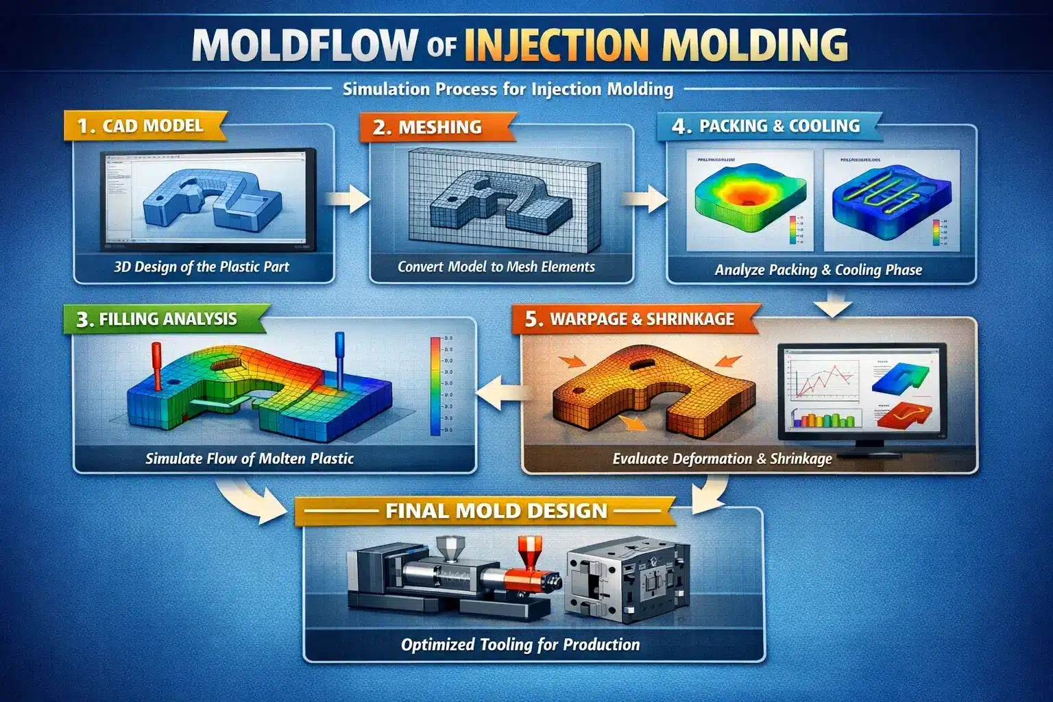
Moldflow (the generic term for injection mold filling simulation, with Autodesk Moldflow being the dominant commercial platform) predicts how molten plastic moves through a mold cavity before the steel is cut. It models fill pattern, pressure drop, cooling uniformity, shrinkage, weld line location, air trap formation, and warpage. Done right, it converts guesswork into engineering decisions.
But not every project needs it. Running full simulation on a flat polypropylene bracket with a single gate wastes budget. Skipping it on a thin-wall medical housing with four gates and a tight flatness tolerance wastes far more.
This article gives engineers and sourcing professionals a clear, technically grounded framework for making that call. For a broader overview of how the process works end-to-end, see our injection molding comprehensive guide.
What Does Moldflow Actually Analyze?
Moldflow simulation covers several distinct analysis modules. Understanding what each does helps you scope the right study for the right problem — instead of ordering a full analysis when fill-only would suffice.
| Analysis Module | What It Predicts | When You Need It |
|---|---|---|
| Fill analysis | Flow front, short shots, weld/knit lines, air traps | Almost always — the baseline module |
| Pack/hold analysis | Sink marks, volumetric shrinkage, gate freeze time | Whenever cosmetic finish or dimensional tolerance matters |
| Cool analysis | Mold temperature distribution, cycle time, hot spots | Multi-cavity molds, complex cooling layouts, high-volume production |
| Warp analysis | Part deflection and distortion after ejection | Precision parts, thin-wall parts, crystalline polymers |
| Fiber orientation (GF) | Anisotropic shrinkage in glass-filled materials | Any part molded in glass-reinforced resin |
| Gate location optimization | Optimal gate position to balance fill and minimize defects | Complex geometries with multiple feasible gate locations |
Most commercial moldflow studies bundle fill + pack + warp as a standard package. Cool analysis is often quoted separately and is substantially more compute-intensive. For a practical look at how gate positioning interacts with simulation results, see why and where to set gates for injection molding.
When Is Moldflow Mandatory?
1. The Part Uses a Crystalline or Glass-Filled Polymer
Crystalline materials — polypropylene (PP), nylon (PA6, PA66), acetal (POM), PBT, PET, PEEK — exhibit anisotropic shrinkage. Shrinkage in the flow direction differs from shrinkage perpendicular to flow. For amorphous materials like ABS or PC, shrinkage is isotropic and falls in the 0.000–0.005 in./in. range. Crystalline polymers can shrink above 0.010 in./in., and that shrinkage varies by orientation.
When you add glass fiber, shrinkage drops significantly in the flow direction but remains higher transverse to flow. Moldflow’s fiber orientation module predicts where fibers align, allowing accurate warpage calculation. Without it, tooling engineers are guessing at compensation values. Understanding how glass fiber affects the molded surface and structural behavior is essential context before running a fiber orientation study.
The rule: Any part in a glass-filled or crystalline polymer with functional dimensional requirements needs at minimum fill + warp analysis.
2. The Part with Thin Walls or Varying Wall Thickness
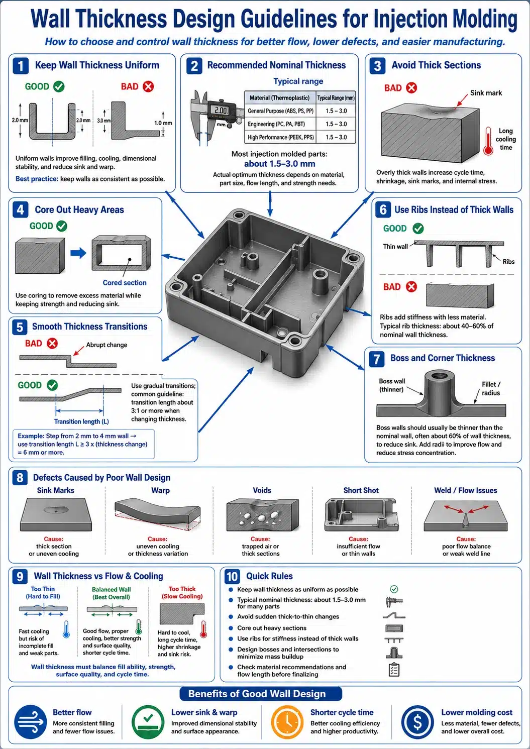
Cooling time scales with the square of wall thickness. A part with 0.060 in. walls cycles in approximately 18 seconds total; the same part at 0.100 in. walls needs around 28 seconds. When wall thickness varies significantly across the same part, differential cooling creates internal stress and warpage — and differential fill creates race-tracking, where thin sections fill last, trapping air.
Moldflow identifies exactly where flow hesitation occurs and where differential pack pressure leaves residual sink or void. For the full engineering relationship between wall thickness, gate placement, and mold cost, see how wall thickness and gate design affect mold cost. Design guidelines for wall sections are covered in detail in draft angle and wall thickness.
Thin-wall threshold: Parts with nominal walls below 1.5 mm (0.060 in.) or wall thickness variation exceeding a 3:1 ratio within the same part require fill and pack analysis.
3. The Part Has Multiple Gates
Every additional gate introduces a weld line where two flow fronts meet. Weld lines are not just cosmetic — they represent a plane of weakness where polymer chains have not had time to fully inter-diffuse. The strength of a weld line depends on melt temperature, flow front velocity, and how much pressure is available at the meeting point.
Moldflow predicts weld line location with high accuracy so engineers can reposition gates, adjust injection speed profiles, or modify geometry to move weld lines away from load-bearing surfaces or cosmetic Class A faces. This is especially critical in automotive interior components or structural brackets. The relationship between gate type, location, and fill behavior is foundational — review common rules for runner systems alongside any simulation work.
4. The Mold Is Multi-Cavity (4 Cavities or More)
In a multi-cavity mold, unbalanced runner systems cause cavities to fill at different rates and pressures. The first-to-fill cavities flash; the last-to-fill cavity short-shots. A naturally balanced runner layout eliminates this — but only if runner diameters and gate dimensions are correctly sized.
Every 90° turn in a runner increases required runner diameter by 20%, and runner diameters scale with both material viscosity and flow length. For ABS over a 10-inch runner, minimum full-round diameter is 0.156 in. (3.9 mm); for nylon 6/6 over the same length, 0.093 in. (2.4 mm) suffices. Scaling these correctly across a 16-cavity hot manifold requires simulation. See also our comparison of two-plate, three-plate, and hot runner mold systems for context on which configuration benefits most from flow analysis.
The rule: Any cold-runner mold with more than two cavities, and any hot-runner manifold regardless of cavity count, benefits materially from flow balance analysis.
5. The Part Has a Strict Flatness, Parallelism, or Roundness Tolerance
Warpage is the single most common reason injection-molded parts fail dimensional inspection. It is also the hardest defect to correct after steel is cut, because the fix may require changing gate location, cooling layout, or process parameters — all of which interact.
Moldflow warp analysis predicts the deflected shape of the part after ejection and cooling, accounting for differential shrinkage and frozen-in stress. For medical device housings, automotive sensor brackets, or connector bodies with sub-millimeter flatness tolerances, the simulation result drives both tooling design decisions and process window definition before T1. The downstream quality impact of tolerance failures is detailed in injection molding tolerances and their impact on part quality.
Correcting warp after T1 typically costs 2–5× more than preventing it at the design stage.
6. The Mold Is a Major Capital Investment
High-cavitation production tools in hardened H-13 or P-20 mold steel with hot runner systems commonly represent $80,000–$400,000 in tooling investment. At that spend level, spending $3,000–$8,000 on a moldflow study to validate the design before machining begins is straightforward risk management. Scrapping or extensively reworking a production mold is not a recoverable situation on a project budget.
For a detailed breakdown of what drives tooling costs and where simulation fits in the investment decision, see mastering injection molding costs and why investing in injection molds is so costly.
7. The Material Is Being Processed Near Its Window Limits
Some materials have narrow processing windows where melt temperature, injection speed, and gate design must all align precisely. PVC — rigid grades in particular — is extremely heat-sensitive and requires consistent cycle times to avoid degradation. PEEK requires mold temperatures of 320–392°F (160–200°C) with oil heating and must not be quenched amorphously. LCP requires high mold temperatures (up to 320°F / 160°C) to achieve good surface finish and low warpage.
For any material with a tight processing window, moldflow identifies whether the cavity can fill completely at pressures and temperatures within the safe operating range — before a molder commits to a gate design that will require excessive injection pressure to fill. The drying requirements and material behavior for hygroscopic resins are equally critical: see injection molding material drying for pre-production preparation guidelines.
When Can You Skip Moldflow?
1. The Part Is Simple, Amorphous, and Cosmetically Non-Critical
A flat polypropylene dust cover, a polyethylene cap, a general-purpose PS enclosure with a single gate and no tight tolerances — these are candidates to skip full simulation. Amorphous materials have isotropic, predictable shrinkage in the 0.000–0.005 in./in. range. Simple geometry produces predictable flow. An experienced molder with a well-designed single gate can hit functional dimensional requirements without simulation.
Use simulation for risk reduction, not for routine. If the part geometry is similar to existing production parts your molder has run with the same resin, experience transfers. Understanding how to identify and classify plastic materials helps determine upfront whether your resin category even warrants simulation.
2. The Part Is a Prototype in Aluminum Tooling
Prototype molds in 7075-T6 aluminum are built for speed and cost efficiency — not long-term optimization. They accept geometric imperfections that a production tool must correct. More importantly, aluminum’s thermal conductivity is approximately 4× higher than steel, which changes the cooling dynamics meaningfully versus the production mold.
Running a detailed moldflow study on aluminum prototype tooling that will not map directly to the production steel mold is often wasted investment. Use prototype trials to observe actual fill behavior, gate freeze behavior, and ejection — then apply that empirical data to the production mold simulation. The full prototyping-to-production pathway is explained in going from prototype to production injection molding.
3. The Mold Is a Direct Copy of a Validated Design
If you are re-cutting an existing production mold that has already been qualified through T1/T2/T3 trials, using the same resin grade, same gate design, and same machine class — moldflow adds minimal value. The processing window is already known. The warpage behavior is documented. The dimensional capability is established.
Moldflow is a predictive tool. When the answer is already proven empirically, prediction is redundant. For guidance on what a proper mold qualification process looks like from trial to sign-off, see the investment process for new plastic molded part development.
What Moldflow Cannot Tell You
Simulation accuracy depends entirely on the accuracy of material data inputs. A moldflow analysis is only as reliable as the viscosity curve, pvT (pressure-volume-temperature) data, and thermal conductivity values loaded into the material database. Generic resin entries in commercial simulation databases often differ from the behavior of specific commercial grades.
Moldflow also does not simulate:
- Mold steel mechanical deflection under injection pressure
- Ejector pin stress or part sticking behavior
- Flash formation at parting lines under clamp force
- Mold wear over production life
These require tooling engineering judgment and experience — simulation is a complement to engineering expertise, not a replacement. For a comprehensive look at how common defects are diagnosed and resolved without simulation, see analysis of injection molding defects and their resolution and the injection mold defect and deformation case studies.
The role of Design for Manufacturability (DFM) in injection molding is also inseparable from simulation: DFM catches geometry-level risks that moldflow then quantifies with specific pressure, temperature, and warp predictions.
Frequently Asked Questions
Does moldflow analysis guarantee defect-free parts at T1?
No. Simulation reduces risk by predicting likely defect locations and informing design decisions, but it does not account for every variable, including specific machine characteristics, mold steel deflection, and operator setup variation. T1 trials remain essential for validating the actual physical system. For a structured view of what T1 and subsequent trials entail, see the injection molding product launch milestones guide.
How accurate is moldflow warpage prediction in practice?
For amorphous materials with reliable material data inputs, predicted vs. actual warpage typically agrees within 15–25%. For glass-filled crystalline polymers, accuracy improves significantly when a validated fiber orientation model is used — but results should still be treated as directional guidance, not a precision specification. Always validate warp results against T1 physical measurements alongside your four-stage quality control process.
Can my mold maker run moldflow in-house, or should I use an independent service?
Both options are valid. Many full-service mold makers in the US and China offer in-house simulation capability, which can streamline iteration. Independent simulation firms provide unbiased analysis — useful when you want a second opinion on a toolmaker’s gate and runner recommendations. Verify that whoever runs the analysis uses a validated material database entry for your specific resin grade. When evaluating China-based suppliers for simulation capability, the criteria in the 2026 guide to choosing China injection molding suppliers is a useful starting framework.
At what point in the design process should moldflow be run?
Ideally during the DFM stage — after the part design is functionally stable but before tooling DFM sign-off and steel purchase. Running simulation after the mold cavity has been roughed-out leaves few actionable changes available and most of the tooling budget spent. The 7 crucial DFM questions framework is a practical checklist to run before commissioning any simulation study.
Conclusion
Moldflow simulation is not a checklist item — it is a risk calibration decision. For parts in glass-filled or crystalline polymers, multi-cavity tools, thin walls, or precision tolerances, skipping simulation converts a known design risk into an expensive trial-and-error problem. For simple geometry in amorphous resins with standard tolerances, full simulation may be unnecessary overhead.
The decision belongs at the DFM stage, made by engineers with access to part geometry, material specification, production volume, and tooling investment data — not after the purchase order for steel has already been placed. If you are unsure which category your part falls into, start with the DFM review process and let that assessment determine whether simulation is warranted.
Related Articles — Internal
- Design for Manufacturability (DFM) in Injection Molding
- Why Simulation Is Essential for Injection Molding
- Injection Mold Defect & Deformation Case Studies
- Analysis of Injection Molding Defects and Their Resolution
- Going from Prototype to Production Injection Molding
- Injection Molding Tolerances and Their Impact on Part Quality
- 7 Crucial Questions to Ask When Evaluating DFM
External References

