Injection Molding Gate Design: 9 Gate Types and How to Choose the Right One
Gate design is one of the smallest but most important decisions in plastic injection mold design. The gate type, size, and location directly affect filling balance, weld lines, sink marks, warpage, gate vestige, cycle time, and trimming cost.
Quick Answer: What Is the Best Gate Type?
There is no single best injection molding gate for every plastic part. The correct gate depends on part geometry, wall thickness, plastic material, cosmetic requirements, production volume, runner system, and degating method. Edge gates are simple and low cost, fan gates are useful for wide flat parts, submarine gates allow automatic degating, and pinpoint gates are often used in three-plate molds for small or cosmetic components.
What Is a Gate in Injection Molding?
In injection molding, the gate is the narrow opening between the runner system and the mold cavity. Molten plastic flows through the gate into the cavity, fills the part, and then the gate freezes to help maintain packing pressure inside the molded part.
A well-designed gate helps the molten resin enter the cavity quickly and uniformly. After filling, the gate should freeze at the right time to prevent backflow and maintain enough packing pressure. Poor gate design can cause shrinkage, dents, short shots, flow marks, weld lines, burning, or part deformation. To understand the full context of how a gate fits into the overall process, see our plastic molding process cycle overview.
Why Gate Design Matters
Gate design affects part quality
Gate position controls how plastic flows into the cavity. If the gate is placed in the wrong area, the melt front may create weak weld lines, trapped air, uneven shrinkage, or visible surface defects.
Gate design affects production cost
Some gates require manual trimming, while others can be automatically separated during ejection. Gate choice influences cycle time, runner waste, mold complexity, maintenance, and secondary finishing cost. Learn more about how these decisions affect your budget in our injection molding cost guide.
Designing a Gate: 6 Practical Principles
Before selecting a gate type, the mold designer should evaluate the part structure, material flow, appearance requirements, strength areas, shrinkage direction, and runner balance. These principles also apply during Design for Manufacturability (DFM) review.
Gate Into a Thick Area
Place the gate near the thickest practical wall section so the plastic can flow from thick to thin areas and maintain better packing pressure.But jetting should be avoided
Keep Flow Path Short
A shorter flow path reduces pressure loss, heat loss, filling difficulty, and risk of short shots.
Avoid Cosmetic Surfaces
Gate marks should be positioned on hidden, non-cosmetic, or easy-to-trim areas whenever possible.
Control Weld Lines
Do not place weld lines in critical strength areas, screw bosses, clips, hinges, sealing surfaces, or transparent areas.
Protect Cores and Inserts
Avoid direct melt impact on thin cores, inserts, sliders, lifters, or fragile mold features to reduce deformation and damage.
Balance Multi-Cavity Molds
For multi-cavity molds, each cavity should receive similar pressure, temperature, and filling time to reduce part variation.
Gate Location Video
The video below shows how gate position influences melt flow and cavity filling.
Injection Molding Gate Type Comparison
Use this table as a quick selection guide before reading the detailed explanations below.
| Gate Type | Best For | Typical Size | Advantages | Limitations | Degating | Gate Mark |
|---|---|---|---|---|---|---|
| Edge Gate | General plastic parts, flat parts, low-cost molds | h 0.5–2.0 mm, w 1.5–5 mm, L 0.5–2.0 mm | Simple, easy to machine, low mold cost | Visible gate mark, usually needs trimming | Manual | Medium |
| Fan Gate | Large flat parts and wide surfaces | h 0.5–1.5 mm, B up to 10–30 mm, L 0.7–2 mm | Better melt distribution, helps reduce warpage | Larger vestige, more difficult trimming | Manual | Large |
| Diaphragm Gate | Cylindrical or hollow parts requiring concentricity | Thickness 0.2–0.8 mm, full circumference | Balanced filling around the part | Gate removal may leave rough edge | Manual | Large |
| Ring Gate | Cylindrical parts where internal accuracy matters | Thickness 0.3–0.8 mm, width matched to circumference | Uniform filling around circular parts | Requires careful gate land control | Manual | Medium to large |
| Spoke Gate | Large cylindrical or thick-section parts | — | Allows high material throughput | May reduce weld strength and require machining | Manual | Large |
| Tunnel / Submarine Gate | Small to medium parts, hidden gate areas | d 0.8–1.5 mm (small), 1.5–2.2 mm (large); angle 35°–45° | Automatic degating, clean production | More complex machining, venting must be considered | Automatic | Small to medium |
| Pinpoint Gate | Three-plate molds, small cosmetic parts | d 0.5–1.5 mm (cold runner); taper 15°–30° | Automatic degating and small gate mark | Higher mold cost, gate wear risk with filled materials | Automatic | Small |
| Tab Gate | Decorative housings and parts sensitive to jetting | — | Reduces jetting and flow marks | Expensive or difficult to remove | Manual | Large |
| Film / Flash Gate | Wide flat parts with warpage concerns | Thickness 0.2–0.8 mm, full part width | Wide, even filling across the part edge | Secondary trimming can be troublesome | Manual | Very large |
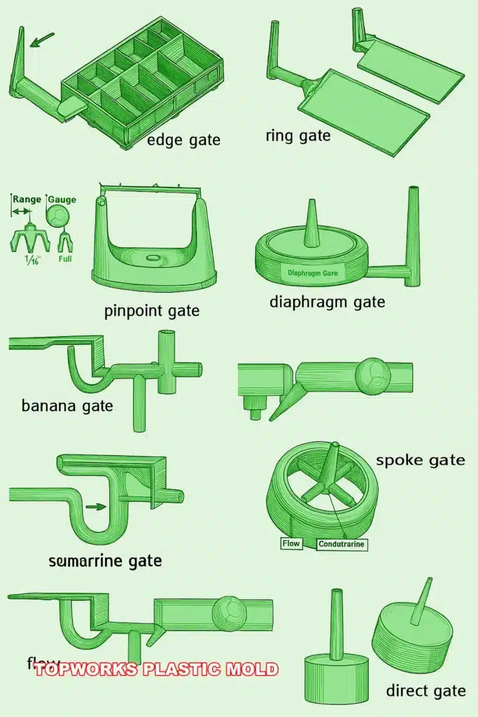
9 Common Injection Molding Gate Types
Each gate design has a different balance of mold cost, cosmetic quality, trimming method, flow control, and production efficiency.

1. Edge Gate
The edge gate, also called a side gate, is one of the simplest and most widely used gate designs. It is easy to machine and suitable for many general-purpose plastic parts.
- Best for: flat parts, covers, boxes, and non-critical cosmetic areas.
- Advantages: simple structure, easy modification, low mold cost.
- Limitations: visible gate mark and secondary trimming are usually required.
| Wall Thickness T (mm) | Depth h (mm) | Width b (mm) | Land L (mm) |
|---|---|---|---|
| < 0.8 | ≈ 0.5 | ≈ 1.0 | 1.0 |
| 0.8 – 1.5 | 0.6 – 0.8 | 1.0 – 1.5 | 1.0 – 1.2 |
| 1.5 – 2.5 | 0.8 – 1.2 | 1.5 – 2.5 | 1.0 – 1.5 |
| 2.5 – 4.0 | 1.2 – 2.0 | 2.5 – 4.0 | 1.2 – 1.8 |
| > 4.0 | 2.0+ | 4.0+ | 1.5 – 2.0 |
Gate depth h is the most critical dimension — it controls gate freeze time and packing. Gate cross-section area is typically 3%–9% of the runner cross-section.

2. Fan Gate
A fan gate is an extended version of the edge gate. It spreads molten plastic over a wider entrance, which can help fill large flat areas more evenly.
- Best for: large flat plastic parts and panels.
- Advantages: improves melt distribution and may reduce flow marks or warpage.
- Limitations: the gate is large and removal may leave a visible trace.
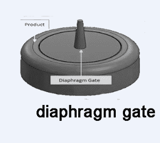
3. Diaphragm Gate
Diaphragm or disc gates are commonly used for cylindrical or hollow components where concentricity and weld strength are important.
- Best for: tubes, bushings, circular parts, and hollow components.
- Advantages: balanced filling around the circumference.
- Limitations: gate removal may leave a sharp or rough edge.
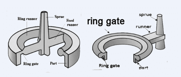
4. Ring Gate
Ring gates are often used on cylindrical moldings when internal dimensions are more critical than external appearance.
- Best for: cylindrical parts requiring uniform circular filling.
- Advantages: helps maintain balanced flow and packing.
- Limitations: gate land depth must be controlled carefully to avoid degating problems.

5. Spoke Gate
Spoke gates can be used when a part is too large for diaphragm or ring gating. They allow a larger volume of plastic to enter the cavity.
- Best for: thicker cylindrical parts and high shot weight moldings.
- Advantages: greater material throughput and packing control.
- Limitations: may reduce weld strength and often requires machining after molding.

6. Tunnel or Submarine Gate
A tunnel gate, also called a submarine gate, allows the part to separate automatically from the runner during ejection. This is useful for high-volume production.
- Best for: small to medium parts where automatic degating is required.
- Advantages: reduces manual trimming and improves production efficiency.
- Limitations: needs good venting because gas trapping and burn marks can occur. See our guide on injection mold venting for details.

7. Pinpoint Gate
Pinpoint gates are commonly used in three-plate molds. They create a small gate mark and allow automatic runner separation during mold opening. For a comparison of two-plate, three-plate, and hot runner systems, see our mold type guide.
- Best for: small cosmetic parts, precision parts, and multi-cavity molds.
- Advantages: small vestige and automatic degating.
- Limitations: higher mold cost and gate wear risk with glass-filled or abrasive materials.
For ABS / PS: prefer d 0.8–1.2 mm. For PC / PMMA / POM: use d 1.2–2.0 mm to avoid high shear and burning.
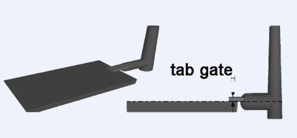
8. Tab Gate
A tab gate introduces molten plastic through a tab feature rather than directly into the part. This helps reduce jetting, worming, and stress-related distortion.
- Best for: decorative housings, instrument cases, and parts where jetting must be avoided.
- Advantages: smoother flow transition and better surface quality.
- Limitations: tab removal can be expensive or difficult.

9. Flash or Film Gate
A film gate is similar to a very wide fan gate. It is used when a large flat part needs uniform filling across a broad edge.
- Best for: wide flat parts and panels where warpage must be controlled.
- Advantages: provides broad, even material flow.
- Limitations: post-molding trimming can be time-consuming and may affect appearance.
Common Gate Design Mistakes
Many molding defects are not caused by the injection machine alone. Poor gate design can create quality issues even when the mold steel and machine settings are correct. For a deeper look at how these issues manifest, see our injection molding defects analysis. The troubleshooting guide also covers root-cause solutions for common defects related to gate placement and sizing. Industry researchers at ScienceDirect and the Society of Plastics Engineers (SPE) provide additional technical references on flow simulation and gate optimization.
Gate Too Small
A gate that is too small may freeze too early, causing short shots, sink marks, poor packing, high injection pressure, and weak weld lines.
Gate Too Large
A gate that is too large may leave a visible vestige, increase trimming cost, extend cooling time, and create stress near the gate area.
Gate Selection Rule of Thumb
Use edge gates for simple and low-cost structural parts, fan gates for large flat parts, submarine gates when automatic degating is needed, pinpoint gates for three-plate molds and small cosmetic components, and film gates for wide parts that need even flow across a broad edge.
For high-volume cosmetic parts or engineering components, gate selection should be confirmed with DFM review, mold flow analysis, material shrinkage data, and production requirements.
General sizing rules: Gate cross-section area = 3%–9% of runner cross-section area. Gate height h ≈ 0.5–0.75 × local wall thickness T as starting point. Gate land length: 0.5–1.0 mm for thin-wall parts; 1.0–1.5 mm for thick-wall parts. Maximum flow length ratio: L/T ≤ 150 (e.g. T = 1.5 mm → max flow length ≈ 225 mm). For glass-fiber reinforced materials, increase gate cross-section by approximately 10% to reduce shear. See also our article on preventing glass-fiber rich surfaces.
FAQ: Injection Molding Gate Design
What is the best gate type for cosmetic plastic parts?
Submarine gates, pinpoint gates, or hot runner gates are often preferred for cosmetic parts because they can reduce visible gate marks. The final choice depends on part geometry, material, and allowed gate location.
Which gate type is best for automatic degating?
Tunnel or submarine gates and pinpoint gates are commonly used for automatic degating. Submarine gates shear off during ejection, while pinpoint gates separate during three-plate mold opening.
How does gate size affect sink marks?
If the gate is too small or freezes too early, packing pressure may not be maintained long enough. This can increase the risk of sink marks, voids, or dimensional instability. Our sink mark solution guide explains how gate sizing, cooling, and packing settings interact.
Where should the gate be placed on a plastic part?
The gate should normally be placed near a thick section, away from cosmetic surfaces, away from strength-critical weld line areas, and positioned to create a short and balanced flow path. The 8 key considerations for injection molding design covers gate placement alongside other critical design factors.
What is the difference between a submarine gate and a pin gate?
A submarine gate is angled below the parting line and usually separates during ejection. A pin gate is usually used in a three-plate mold and separates when the runner plate opens.
When should mold flow analysis be used for gate design?
Mold flow analysis is useful for large parts, thin-wall parts, multi-cavity molds, high-cosmetic parts, glass-filled materials, and parts with strict warpage or dimensional requirements. Read our full breakdown of AI-driven mold flow analysis to understand when simulation is most valuable. The Autodesk Moldflow platform is one of the industry-standard tools used for this purpose.
Need Help Choosing the Right Gate for Your Plastic Part?
Topworks can review your 3D part design, suggest a suitable gate type, check possible weld lines, evaluate parting line and ejection layout, and help optimize your plastic injection mold before production.
Related Injection Molding Resources

