
Injection Molding Gate Design: 9 Gate Types and How to Choose the Right One
Gate design is the smallest call in the whole mold. It still causes the most defects. Gate type, size, and location drive filling balance, weld lines, sink, and warpage. The same choices set vestige, cycle time, and trimming cost. Pick wrong and you bleed money. Every shot.
Quick Answer: What Is the Best Gate Type?
There’s no single best injection molding gate for every plastic part. The right gate depends on geometry, wall thickness, and material. It also depends on cosmetics, volume, runner system, and degating. Edge gates are simple and cheap. Fan gates suit wide flat parts. Submarine gates degate themselves. Pinpoint gates fit three-plate molds for small or cosmetic parts.
What Is a Gate in Injection Molding?
The gate is the narrow opening between the runner and the cavity. Melt flows through it into the cavity and fills the part. Then the gate freezes. That freeze holds packing pressure inside the part.
A good gate lets resin enter the cavity fast and evenly. It should freeze at the right moment after filling. Freeze too early or too late and you get backflow or weak packing. Bad gate design causes sink, short shot, flow marks, weld lines, burning, or warpage. Want the bigger picture? See our plastic molding process cycle overview.
Why Gate Design Matters
Gate design affects part quality
Gate position controls how the melt flows in. Put it in the wrong spot and the melt front goes bad. You get weak weld lines, trapped air, uneven shrinkage, or surface defects.
Gate design affects production cost
Some gates need manual trimming. Others snap off on their own during ejection. Gate choice drives cycle time, runner waste, mold complexity, and finishing cost. That adds up fast. See how it hits your budget in our injection molding cost guide.
Designing a Gate: 6 Practical Principles
Before you pick a gate type, read the part first. Check structure, melt flow, appearance, strength areas, shrinkage direction, and runner balance. These rules also apply during Design for Manufacturability (DFM) review.
Gate Into a Thick Area
Gate near the thickest practical wall. Melt should flow from thick to thin. That keeps packing pressure up. But watch for jetting.
Keep Flow Path Short
Short flow path, less pressure loss. It also cuts heat loss and filling trouble. Fewer short shots.
Avoid Cosmetic Surfaces
Keep the gate mark off show surfaces. Hide it, or put it where trimming is easy.
Control Weld Lines
Never drop weld lines on load-bearing spots. That means screw bosses, clips, hinges, seals, and clear areas.
Protect Cores and Inserts
Don’t blast melt straight at thin cores or inserts. Same for sliders and lifters. Direct impact bends and breaks them.
Balance Multi-Cavity Molds
In a multi-cavity mold, every cavity needs the same deal. Same pressure, same temp, same fill time. Otherwise parts vary.
Gate Location Video
Watch how gate position changes melt flow and cavity filling.
Injection Molding Gate Type Comparison
Scan this table to narrow your choice. The full breakdown sits below.
| Gate Type | Best For | Typical Size | Advantages | Limitations | Degating | Gate Mark |
|---|---|---|---|---|---|---|
| Edge Gate | General plastic parts, flat parts, low-cost molds | h 0.5–2.0 mm, w 1.5–5 mm, L 0.5–2.0 mm | Simple, easy to machine, low mold cost | Visible gate mark, usually needs trimming | Manual | Medium |
| Fan Gate | Large flat parts and wide surfaces | h 0.5–1.5 mm, B up to 10–30 mm, L 0.7–2 mm | Better melt distribution, helps reduce warpage | Larger vestige, more difficult trimming | Manual | Large |
| Diaphragm Gate | Cylindrical or hollow parts requiring concentricity | Thickness 0.2–0.8 mm, full circumference | Balanced filling around the part | Gate removal may leave rough edge | Manual | Large |
| Ring Gate | Cylindrical parts where internal accuracy matters | Thickness 0.3–0.8 mm, width matched to circumference | Uniform filling around circular parts | Requires careful gate land control | Manual | Medium to large |
| Spoke Gate | Large cylindrical or thick-section parts | — | Allows high material throughput | May reduce weld strength and require machining | Manual | Large |
| Tunnel / Submarine Gate | Small to medium parts, hidden gate areas | d 0.8–1.5 mm (small), 1.5–2.2 mm (large); angle 35°–45° | Automatic degating, clean production | More complex machining, venting must be considered | Automatic | Small to medium |
| Pinpoint Gate | Three-plate molds, small cosmetic parts | d 0.5–1.5 mm (cold runner); taper 15°–30° | Automatic degating and small gate mark | Higher mold cost, gate wear risk with filled materials | Automatic | Small |
| Tab Gate | Decorative housings and parts sensitive to jetting | — | Reduces jetting and flow marks | Expensive or difficult to remove | Manual | Large |
| Film / Flash Gate | Wide flat parts with warpage concerns | Thickness 0.2–0.8 mm, full part width | Wide, even filling across the part edge | Secondary trimming can be troublesome | Manual | Very large |
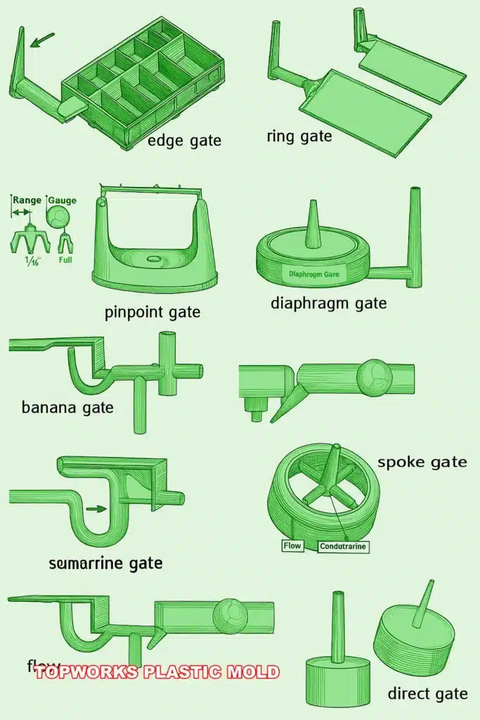
9 Common Injection Molding Gate Types
Every gate trades off something. Mold cost, looks, trimming, flow control, output speed. Pick the trade you can live with.

1. Edge Gate
The edge gate, or side gate, is the workhorse. Easy to cut, cheap to build, fits most general parts.
- Best for: flat parts, covers, boxes, non-cosmetic faces.
- Advantages: simple, easy to tweak, cheap mold.
- Limitations: visible mark, and you’ll usually trim it by hand.
| Wall Thickness T (mm) | Depth h (mm) | Width b (mm) | Land L (mm) |
|---|---|---|---|
| < 0.8 | ≈ 0.5 | ≈ 1.0 | 1.0 |
| 0.8 – 1.5 | 0.6 – 0.8 | 1.0 – 1.5 | 1.0 – 1.2 |
| 1.5 – 2.5 | 0.8 – 1.2 | 1.5 – 2.5 | 1.0 – 1.5 |
| 2.5 – 4.0 | 1.2 – 2.0 | 2.5 – 4.0 | 1.2 – 1.8 |
| > 4.0 | 2.0+ | 4.0+ | 1.5 – 2.0 |
Gate depth h is the most critical dimension — it controls gate freeze time and packing. Gate cross-section area is typically 3%–9% of the runner cross-section.

2. Fan Gate
A fan gate is an edge gate stretched wide. It spreads melt across a broad opening. Big flat areas fill more evenly.
- Best for: large flat parts and panels.
- Advantages: better melt spread, fewer flow marks and less warpage.
- Limitations: the gate is big, and removal leaves a trace.
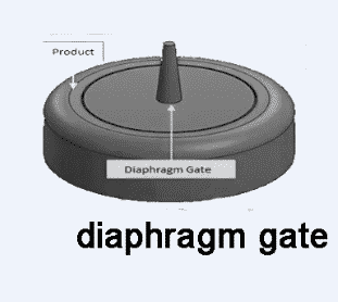
3. Diaphragm Gate
Diaphragm or disc gates suit round and hollow parts. Use them when concentricity and weld strength matter.
- Best for: tubes, bushings, round parts, hollow parts.
- Advantages: even filling all the way around.
- Limitations: removal can leave a sharp or rough edge.
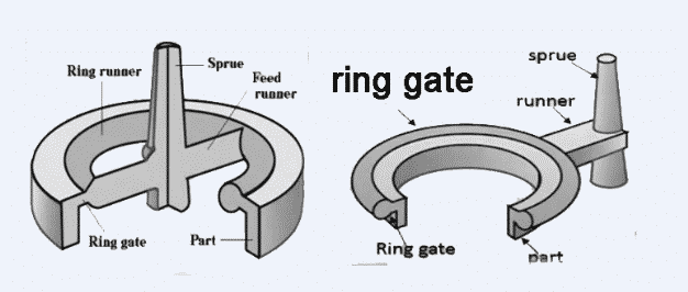
4. Ring Gate
Ring gates fit cylindrical parts. Reach for one when inside dimensions matter more than the outside look.
- Best for: cylindrical parts needing even circular fill.
- Advantages: balanced flow and packing.
- Limitations: gate land depth needs tight control, or degating fails.

5. Spoke Gate
Spoke gates step in when a part is too big for diaphragm or ring gating. They push more plastic into the cavity.
- Best for: thicker cylindrical parts, high shot weight.
- Advantages: high throughput and packing control.
- Limitations: can weaken welds, often needs machining after molding.

6. Tunnel or Submarine Gate
A tunnel gate, or submarine gate, shears off by itself during ejection. The part drops free of the runner. Great for high volume.
- Best for: small to medium parts that need automatic degating.
- Advantages: cuts manual trimming, speeds up the run.
- Limitations: needs good venting, or gas traps and burn marks show up. See our guide on injection mold venting for details.

7. Pinpoint Gate
Pinpoint gates live in three-plate molds. They leave a tiny mark. The runner separates on its own as the mold opens. Comparing two-plate, three-plate, and hot runner setups? See our mold type guide.
- Best for: small cosmetic parts, precision parts, multi-cavity molds.
- Advantages: small vestige, automatic degating.
- Limitations: pricier mold, and the gate wears with glass-filled or abrasive resins.
For ABS / PS: prefer d 0.8–1.2 mm. For PC / PMMA / POM: use d 1.2–2.0 mm to avoid high shear and burning.
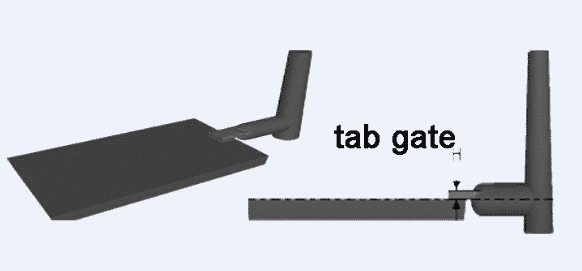
8. Tab Gate
A tab gate feeds melt through a tab, not straight into the part. That tab kills jetting, worming, and stress distortion.
- Best for: decorative housings, instrument cases, parts that jet easily.
- Advantages: smoother flow, better surface.
- Limitations: the tab is a pain to remove, and removal costs money.

9. Flash or Film Gate
A film gate is basically a very wide fan gate. Use it when a big flat part needs even fill across one long edge.
- Best for: wide flat parts and panels where warpage is a worry.
- Advantages: broad, even material flow.
- Limitations: trimming eats time and can mark the surface.
Common Gate Design Mistakes
Don’t blame the machine for every defect. Bad gate design wrecks quality even with good steel and correct settings. Want to see how it shows up? Read our injection molding defects analysis. The troubleshooting guide digs into root causes tied to gate placement and sizing. Researchers at ScienceDirect and the Society of Plastics Engineers (SPE) cover flow simulation and gate design in depth.
Gate Too Small
Too small a gate freezes early. Then you fight short shots, sink, and high injection pressure. Welds come out weak.
Gate Too Large
Too big a gate leaves an ugly vestige. Trimming cost climbs and cooling drags out. Stress builds near the gate.
Gate Selection Rule of Thumb
Edge gates for simple, low-cost structural parts. Fan gates for large flat parts. Submarine gates when you need automatic degating. Pinpoint gates for three-plate molds and small cosmetic parts. Film gates for wide parts needing even flow across a long edge.
Running high-volume cosmetic or engineering parts? Confirm the gate with DFM review, mold flow analysis, shrinkage data, and your production needs.
General sizing rules: Gate cross-section area = 3%–9% of runner cross-section area. Gate height h ≈ 0.5–0.75 × local wall thickness T as starting point. Gate land length: 0.5–1.0 mm for thin-wall parts; 1.0–1.5 mm for thick-wall parts. Maximum flow length ratio: L/T ≤ 150 (e.g. T = 1.5 mm → max flow length ≈ 225 mm). For glass-fiber reinforced materials, increase gate cross-section by approximately 10% to reduce shear. See also our article on preventing glass-fiber rich surfaces.
FAQ: Injection Molding Gate Design
What is the best gate type for cosmetic plastic parts?
For cosmetic parts, use submarine, pinpoint, or hot runner gates. They cut the visible gate mark. The final call depends on geometry, material, and where you’re allowed to gate.
Which gate type is best for automatic degating?
Submarine gates and pinpoint gates handle automatic degating best. Submarine gates shear off during ejection. Pinpoint gates separate when the three-plate mold opens.
How does gate size affect sink marks?
A small gate that freezes early can’t hold packing pressure. Then sink, voids, and unstable dimensions creep in. Our sink mark solution guide shows how gate size, cooling, and packing settings work together.
Where should the gate be placed on a plastic part?
Place the gate near a thick section. Keep it off cosmetic faces and away from weld-critical zones. Aim for a short, balanced flow path. The 8 key considerations for injection molding design covers gate placement and more.
What is the difference between a submarine gate and a pin gate?
A submarine gate sits angled below the parting line. It shears off during ejection. A pin gate runs in a three-plate mold. It breaks free when the runner plate opens.
When should mold flow analysis be used for gate design?
Run mold flow analysis on large parts, thin-wall parts, and multi-cavity molds. Use it for high-cosmetic parts and glass-filled resins too. Tight warpage or dimensional specs? Simulate first. Read our AI-driven mold flow analysis breakdown for when it pays off. The Autodesk Moldflow platform is one industry-standard tool for this.
Need Help Choosing the Right Gate for Your Plastic Part?
Send us your 3D part. We’ll suggest a gate type and flag likely weld lines. We check parting line and ejection layout too. Then we tighten the mold before you cut steel.
Related Injection Molding Resources

