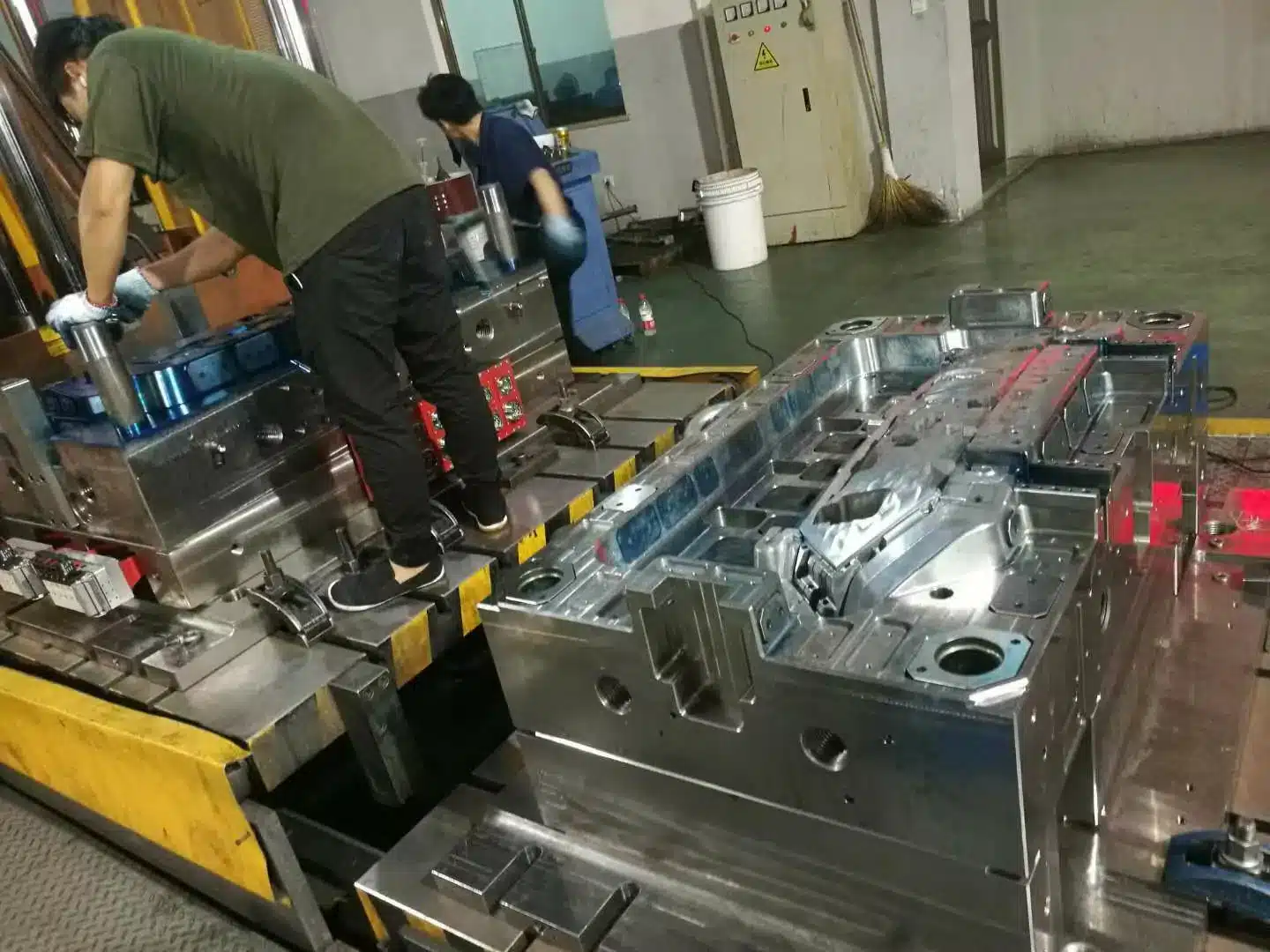

Everything on this page is available as a free, interactive injection molding resource—ready to use online and easy to add to your own website.
Explore a six-stage injection molding cycle simulator and adjust key parameters such as melt temperature, injection speed, and packing pressure to see how they affect part quality and common molding defects in real time. You can also explore practical, interactive guides covering wall thickness, ribs, bosses, draft angles, gates, cooling-system layouts, and essential mold components.
For production and costing, the toolkit includes a clamping-force calculator, landed-cost estimator, and mold-steel selection tool, plus a troubleshooting guide covering 17 common injection molding defects and their potential causes.
Many of these resources also include a ready-to-use embed code. Simply copy and paste the snippet into your website, blog, or WordPress page and provide your visitors with useful molding tools at no cost. A small Topworks credit link is automatically included, so you’re welcome to share and embed any tool that fits your audience’s needs.
10-Step Product Development Workflow

Defining Requirements
Pin down function, load cases, operating environment, regulatory targets, volume and the cost ceiling before anything is drawn. Vague specs here turn into expensive rework at the tooling stage.
Copy & paste the code below. It embeds this workflow on your site and includes a small credit link back to us.
The standard gate at the parting line, feeding the edge of the part. Easy to machine and maintain and suits most geometries, but it leaves a visible mark and needs secondary trimming.
A widened edge gate that fans out before the cavity. It spreads melt across wide, flat or optical parts to reduce warpage, jetting and stress — at the cost of a larger area to trim.
Melt enters a small sacrificial tab first, then the part. This keeps gate stress and jetting off cosmetic surfaces; the tab is trimmed afterwards. Common for thin, transparent or high-stress parts.
A tiny round gate used in 3-plate molds. It breaks off and self-separates from the runner, leaving a very small mark and allowing central or multi-point gating. Needs higher injection pressure.
The gate tunnels below the parting line into the side of the part. It is self-degating — the part shears off the runner on ejection with no trimming — which suits automated, high-volume production.
A curved tunnel gate that reaches onto hidden or inner surfaces, keeping the gate mark off visible faces while staying self-degating. It needs careful design and a consumable insert.
The sprue feeds the cavity directly with no runner — ideal for single, large or deep-draw parts and strong flow. It leaves a large gate mark that must be machined and can add stress.
A heated nozzle keeps plastic molten right up to the gate, so there is no runner scrap. A hot tip leaves a small thermal gate; a valve gate uses a pin for a clean, mark-free, precisely timed gate. Higher tooling cost, best at high volume.
Injection Mold Structure
Interactive Engineering Guide — Click markers to explore components
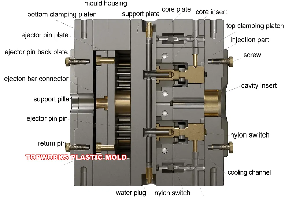
Select a component from the diagram or list to view technical details.
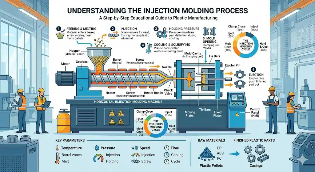
The six stages of injection molding
- Clamping — The two mold halves are closed and locked by the clamping unit before injection begins.
- Injection — Molten resin is injected into the mold cavity at controlled speed and pressure.
- Dwelling (holding) — Holding pressure is maintained to compensate for material shrinkage.
- Cooling — The part solidifies inside the mold; cooling time depends on wall thickness and resin.
- Mold opening — The clamping unit retracts and the mold halves separate.
- Ejection — Ejector pins push the finished part out of the cavity; the cycle repeats.
Click Run to simulate a precision engineering injection molding cycle.
Injection Molding Process Simulator
Adjust parameters with sliders, see real-time effects on part quality and defects
Injection Molding Design Tips
The complete interactive reference for wall thickness, ribs, bosses, draft, undercuts, snap fits, and more
| ABS | 1.1 - 3.5 mm |
| Polycarbonate | 1.0 - 4.0 mm |
| Polypropylene | 0.8 - 3.8 mm |
| Nylon (PA) | 0.8 - 3.0 mm |
| Polyethylene | 0.8 - 5.0 mm |
| POM (Acetal) | 0.8 - 3.0 mm |
- Keep wall thickness uniform throughout the part
- Where thickness must change, use a 3:1 taper ratio
- Thinner walls = faster cooling = shorter cycle time
- Cooling time grows with the square of wall thickness
- Minimum wall depends on flow length and material
| Smooth surfaces | 1 - 2 deg per side |
| Textured surfaces | 1.5 deg + 1 deg per 0.025 mm texture depth |
| Ribs | 0.5 - 1 deg minimum |
| Bosses (inner) | 0.5 - 1 deg |
| Bosses (outer) | 0.5 - 1 deg |
| Deep draws (>50mm) | Add 0.5 deg extra |
- Inside radius: minimum 0.5x wall thickness (T)
- Outside radius: inside radius + wall thickness
- Ideal inside radius: 0.75x T (best flow)
- Never use zero radius - causes 3x stress concentration
- Consistent radii improve flow and reduce cycle time
- Too-large fillets create thick sections (same as boss issue)
- Fillet at parting line: use 0 or match parting to avoid flash
- Reorient the part to align features with pull direction
- Use snap fits with built-in deflection instead of rigid hooks
- Replace side holes with slots open to the parting line
- Use pass-through holes (core from both sides) instead of blind features
- Split the part into two simpler halves that assemble together
- Use shut-off (sliding shutoff) surfaces at parting line for through-holes
- Replace internal threads with external snap features
- Design windows as open on one edge instead of fully enclosed
- Taper cantilever beams (thicker at root) for even stress
- Add radius at the beam root to prevent stress cracking
- Check material allowable strain (varies 1-8% by resin)
- 45 deg entry angle for easy assembly, 90 deg retaining angle for permanence
- Lead-in chamfer on both mating parts for guided assembly
- Lugs/guides to prevent side-loading during engagement
- For repeated assembly, keep strain below 60% of max allowable
- Test prototypes - FEA alone misses creep and fatigue effects
| Polypropylene | Excellent Best choice, flexes millions of cycles |
| Polyethylene | Good Works but less durable than PP |
| Nylon | Limited Low cycle life, needs moisture |
| ABS | Poor Brittle hinge, cracks quickly |
| Polycarbonate | Poor Not suitable for living hinges |
| SPI Grade | Finish | Method | Draft needed | Use case |
|---|---|---|---|---|
| A-1 | Mirror / lens | Diamond buff | 1 deg min | Optical lenses, clear parts |
| A-3 | High gloss | Fine diamond buff | 1 deg min | Consumer electronics |
| B-1 | Semi-gloss | 600 grit paper | 1 deg min | General cosmetic |
| C-1 | Matte | 600 stone | 1.5 deg min | Interior parts |
| D-1 | Sandblast | Dry blast glass bead | 2 deg min | Grip surfaces |
| MT-xxxxx | Mold-Tech texture | Chemical etch | 1.5 deg + 1 deg/0.025mm depth | Leather grain, geometric patterns |
| Linear dimensions | ± 0.1 - 0.3 mm |
| Hole diameters | ± 0.05 - 0.1 mm |
| Flatness | 0.1 - 0.5 mm per 100 mm |
| Across parting line | Add ± 0.1 mm to above |
| Tight (achievable) | ± 0.05 mm with process control |
| High precision | ± 0.025 mm (specialized tooling) |
- Keep critical dimensions on one side of the parting line
- Use datums from features formed by the same mold half
- Expect higher variation across parting line (mold alignment)
- Shrinkage varies by direction (flow vs cross-flow)
- Glass-filled materials have lower, more consistent shrinkage
- Post-mold shrinkage continues for 24-48 hours
- Amorphous resins (ABS, PC) hold tighter tolerances than semi-crystalline (PP, PA)
- Test dimensional stability at expected service temperature
- Gate into the thickest section (pack thin from thick)
- Center gate for radially symmetric parts
- Place gate on non-cosmetic surface
- Gate into a wall to prevent jetting
- Position to push weld lines to non-critical areas
- Use flow simulation to predict weld line locations
- Consider multiple gates for long/complex parts
- Use fan or tab gates for flat parts to reduce stress
- Gate into thin sections (causes hesitation, short shots)
- Gate opposite a boss or pin (creates weak weld line)
- Gate on cosmetic or textured surfaces
- Gate near areas with tight tolerances (high stress zone)
- Place gate where it creates unbalanced flow
- Gate at the end of a long flow path (pressure drop)
- Ignore gate vestige in assembly areas
- Use too-small a gate (excessive shear, burn marks)
- Wall thickness uniform (or gradual 3:1 transitions)
- Ribs at 0.5-0.6x wall, height ≤ 3x wall, spaced ≥ 2x wall
- Bosses at 0.5-0.6x wall, OD = 2x screw diameter, cored 2/3 depth
- Draft of 1-2 deg on all faces (extra for texture)
- Fillets on all inside corners (R ≥ 0.5x T)
- No sharp external corners (minimum 0.5 mm radius)
- Undercuts minimized or eliminated where possible
- Snap fits within material strain limits
- Living hinges only in PP or PE, thickness 0.2-0.5 mm
- Text engraved (not raised) - easier to modify in mold
- Part can be ejected without distortion
- Clear parting line location identified and acceptable cosmetically
- Core and cavity split is feasible (no impossible geometry)
- Draft direction(s) defined for all features
- Side actions identified and justified (each adds cost)
- Ejector pin locations on non-cosmetic surfaces
- Venting locations planned (end of fill, weld lines)
- Cooling channel access for all thick areas
- Gate location(s) selected and cosmetically acceptable
- Runner type chosen (cold/hot) based on volume and material
- Mold steel grade matched to production volume
- Material shrinkage rate accounted for in all dimensions
- Anisotropic shrinkage considered (flow vs cross-flow direction)
- Drying requirements documented (temp, time, dew point)
- Chemical resistance verified for service environment
- UV stability confirmed if outdoor exposure
- Flame rating verified if required (UL 94 V-0, V-2, HB)
- Colorant compatibility confirmed with base resin
- Regrind ratio defined (typically 15-25% max)
- Material flow length verified against part geometry
- Weld line strength acceptable for structural requirements
- Minimize wall thickness (saves material and cycle time)
- Eliminate unnecessary undercuts (fewer side actions)
- Consolidate parts (fewer molds, less assembly)
- Design for auto-degating (submarine or hot-tip gates)
- Minimize post-mold operations (painting, printing, assembly)
- Use family molds for related small parts
- Design for multi-cavity tooling at target volumes
- Use standard mold base sizes when possible
- Consider insert molding to eliminate secondary fastening
- Reduce texture complexity on non-visible surfaces
- Design snap fits to replace screws and adhesives
- Specify loosest acceptable tolerances on non-critical dimensions
Designing Bosses for Injection Molding
Interactive reference: anatomy, boss types, screw details, defects, and material guidelines
| Boss wall (t) | 0.5 - 0.6 x T |
| OD | 2 x screw diameter |
| Max height | ≤ 3 x OD |
| Draft angle | 0.5 - 1 deg per side |
| Base fillet (R) | ≥ 0.25 x T |
| Coring depth | ≥ 2/3 boss height |
- →Pilot hole ID = screw major dia minus one thread depth
- →Thread engagement = 2x to 2.5x screw diameter
- →Add 0.5 mm chamfer at top for screw entry
- →Boss OD = 2x screw major diameter
- →Core the boss from below to eliminate thick sections
- →Hole ID = insert OD (press fit after insertion)
- →Boss OD = insert OD + 2x nominal wall
- →Allow 0.1-0.2 mm radial clearance for knurls
- →Insertion depth at least 1.5x insert length
- →Pre-placed metal inserts need uniform wall around them
- →Boss wall 0.6-0.8x T to resist insert expansion
- →Add undercuts or knurls on insert for retention
- Keep boss wall at 50-60% of nominal wall thickness
- Use gussets or ribs to reinforce tall bosses
- Core bosses from the underside (non-cosmetic surface)
- Add draft of 0.5-1 deg on inner and outer surfaces
- Place bosses away from external corners to ease flow
- Use a fillet radius at the base (min 0.25x T)
- Offset bosses from walls by at least 2x T
- Make boss wall equal to or thicker than the base wall
- Attach bosses directly flush to side walls (use a thin rib)
- Exceed 3x OD for unsupported boss height
- Forget to core - solid bosses always cause sink
- Place bosses too close together (min 2x OD center-to-center)
- Use sharp corners at the base (stress concentrators)
- Ignore mold draft - zero-draft bosses damage the tool
| Parameter | Recommended | Notes |
|---|---|---|
| Boss wall thickness | 0.5 - 0.6 x T | T = nominal part wall thickness |
| Boss OD | 2.0 x screw dia | 2.5x for glass-filled materials |
| Max height | ≤ 3 x OD | Use gussets above 2x OD |
| Draft angle | 0.5 - 1 deg per side | Both inner and outer surfaces |
| Base fillet radius | ≥ 0.25 x T | Larger radii improve flow and strength |
| Coring depth | ≥ 2/3 boss height | Core from non-cosmetic side |
| Rib / gusset thickness | 0.5 x T | Thicker ribs cause sink on opposite face |
| Boss-to-wall offset | ≥ 2 x T | Connect via rib if closer |
| Boss-to-boss spacing | ≥ 2 x OD c-t-c | Prevents merged thick sections |
The standard gate at the parting line, feeding the edge of the part. Easy to machine and maintain and suits most geometries, but it leaves a visible mark and needs secondary trimming.
A widened edge gate that fans out before the cavity. It spreads melt across wide, flat or optical parts to reduce warpage, jetting and stress — at the cost of a larger area to trim.
Melt enters a small sacrificial tab first, then the part. This keeps gate stress and jetting off cosmetic surfaces; the tab is trimmed afterwards. Common for thin, transparent or high-stress parts.
A tiny round gate used in 3-plate molds. It breaks off and self-separates from the runner, leaving a very small mark and allowing central or multi-point gating. Needs higher injection pressure.
The gate tunnels below the parting line into the side of the part. It is self-degating — the part shears off the runner on ejection with no trimming — which suits automated, high-volume production.
A curved tunnel gate that reaches onto hidden or inner surfaces, keeping the gate mark off visible faces while staying self-degating. It needs careful design and a consumable insert.
The sprue feeds the cavity directly with no runner — ideal for single, large or deep-draw parts and strong flow. It leaves a large gate mark that must be machined and can add stress.
A heated nozzle keeps plastic molten right up to the gate, so there is no runner scrap. A hot tip leaves a small thermal gate; a valve gate uses a pin for a clean, mark-free, precisely timed gate. Higher tooling cost, best at high volume.
Manufacturing Logic Simulator
Adjust parameters to find the optimal production method.
🔎 How to Use This Calculator
- Select your resin — picks a reference cavity pressure range automatically.
- Adjust cavity pressure — fine-tune based on wall thickness and gate design.
- Set projected area — measure the largest shadow area of one cavity in cm².
- Choose your cavity layout — 1 to 16 cavities, or enter a custom count.
- Read the results — recommended tonnage, machine utilization gauge, and actionable alerts appear instantly.
Clamping Force & Machine Selection
Injection Molding Decision Tools
Estimate your real cost, pick a surface finish, and match the right mold steel. Figures are planning estimates — send a STEP file for an exact quote.
The quote is not the cost. Add duty, freight, and fees to see what a part really lands at.
SPI finish grades, from optical polish to heavy texture. Click a grade to see what it costs you.
Volume, resin, and finish decide the steel. Pick the wrong grade and you pay in rework or a dead tool.
Estimates for planning only. Final cost, finish, and steel depend on part geometry, tolerance, and volume.
1. Select the defect you need to troubleshoot
Main components of a plastic injection mold
- Core and Cavity — form the shape of the plastic part.
- Runner System — guides molten plastic into the cavity.
- Gate — entry point where plastic flows into the part.
- Cooling Channels — cool the plastic quickly and evenly.
- Ejector Pins — push the finished part out of the mold.
- Slider or Lifter — release side holes and undercuts.
Cooling & Cycle Time Calculator
Cooling typically accounts for 70%–85% of the injection molding cycle. Cooling time is strongly governed by the square of the thickest wall thickness, making wall design and cooling-system performance critical to productivity and part cost.
Planning estimate based on a 1-D transient conduction, center-temperature model. The bare formula gives the theoretical minimum cooling time; the displayed value adds the chosen safety factor to approximate a real production setpoint. Cooling time follows the approximate wall-thickness-squared relationship, and cooling is typically 70%–85% of the molding cycle. Actual cycle time depends on geometry, material grade, crystallization behavior, mold design, cooling-channel layout, coolant temperature, flow regime, machine settings, and ejection requirements.
Injection Molding Resin Selector
Tell us what the part needs and we rank the common molding resins for you — ABS, PP, PC, PA, POM, PMMA and more — with a side-by-side comparison.
| Material | Stiffness | Heat | Impact | Chemical | Cost | Clear | Food | Match |
|---|
Ratings are relative guidance for typical unfilled grades — glass-filled, impact-modified, or specific certified grades differ. Cost ● = higher, ●●●●● = lowest. Confirm food-contact and flammability with the exact grade's datasheet.
How Much Does an Injection Mold Cost?
Estimate the one-time tooling cost of an injection mold from part size, cavity count, complexity, and steel — with a China vs. Western price comparison.
This is the one-time tooling cost — not the per-part price.
Get an exact mold quote — send your STEP file →Planning estimate only. A real mold quote depends on part geometry, tolerance, cavity layout, action count, steel, and runner system. Send a 3D file for a firm price.

