


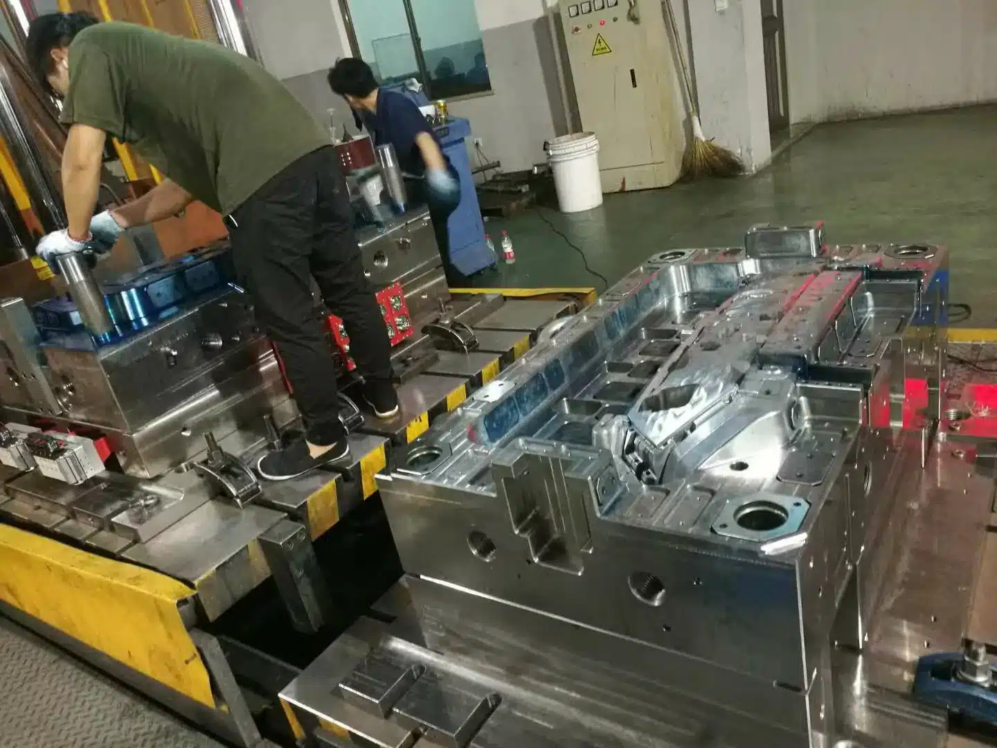

Everything on this page is available as a free, interactive injection molding resource—ready to use online and easy to add to your own website.
Explore a six-stage injection molding cycle simulator and adjust key parameters such as melt temperature, injection speed, and packing pressure to see how they affect part quality and common molding defects in real time. You can also explore practical, interactive guides covering wall thickness, ribs, bosses, draft angles, gates, cooling-system layouts, and essential mold components.
For production and costing, the toolkit includes a clamping-force calculator, landed-cost estimator, and mold-steel selection tool, plus a troubleshooting guide covering 17 common injection molding defects and their potential causes.
Many of these resources also include a ready-to-use embed code. Simply copy and paste the snippet into your website, blog, or WordPress page and provide your visitors with useful molding tools at no cost. A small Topworks credit link is automatically included, so you’re welcome to share and embed any tool that fits your audience’s needs.
Sprue, Runner & Gate — Melt Flow Animation
Intégrez cette animation à votre site
Utilisation gratuite. Merci de conserver le lien vers la source.
Design for Injection Molding — animated
7 rules · what goes wrong vs what to drawEach scene runs the same clock on both halves. Left is the part as engineers usually draw it. Right is the same function, molded correctly. Press play, or drag the timeline to freeze any moment.
Cooling time scales with the square of thickness. An 8 mm (0.31 in) mass needs 7.1× longer to freeze than the 3 mm (0.12 in) wall beside it. The skin solidifies first, then the core shrinks away from it — so you get a sink mark on the outside, a vacuum void on the inside, or both.
Hold one nominal wall and keep every transition inside ±10 %. Core out anything thicker and replace the lost stiffness with ribs. Typical nominal walls: ABS 2.0–3.0 mm (0.079–0.118 in), PP 1.5–3.0 mm (0.059–0.118 in), PC 2.0–3.5 mm (0.079–0.138 in).
Cost hook: cooling is 60–80 % of the cycle. Dropping the thickest section from 8 mm to 3 mm can cut a 60 s cycle to 25–30 s — on 100,000 parts that is more money than the mold.
Send us a STEP file and we will mark up every one of these seven items on your part — wall map, draft check, rib ratios, gate and weld-line plan — before any steel is cut.
Get a free DFM reviewCantilever Snap-Fit — Interactive Assembly Simulator
Drag the slider or press Play. Change the geometry and material to see strain, deflection force and assembly force update in real time.
The cantilever is in its free, unstressed state. Part B travels toward the hook along the insertion axis.
Design parameters
Live results
ε = 1.5·y·t / L² | P = b·t²·E·ε / (6L) | W = P·(μ + tanα) / (1 − μ·tanα). Straight cantilever, constant section. A tapered beam (free-end thickness ≈ 0.5·root) allows roughly 1.6× the deflection at the same strain.
Slide (left)
Lifter (right)
Injection Molding Draft Angle Tool
Set the draft, depth, surface finish and feature type. The tool shows the minimum draft you need, how much the wall grows over the depth, and what happens when the core pulls out.
| Finition de la surface | Typical minimum draft | Where it applies |
|---|
Values are starting points for part design. Texture depth rule of thumb: about 1° extra draft for every 0.025 mm (0.001 in) of etch depth. Confirm the final number with your texture supplier and your mold maker.
Injection Molding DFM Checker
Enter your part's key features. Every change re-scores manufacturability against standard injection molding design rules and tells you what to fix before steel is cut.
Checking…
Click or drag any input on the left: the drawing highlights that feature and its value.
Rules of thumb from common resin-supplier design guides; estimates are indicative. A full DFM review uses your 3D CAD data plus mold-flow simulation.
Cycle de moulage par injection – Étape par étape
Observez un cycle complet sur une machine et une section de moule, puis modifiez l'épaisseur de paroi, la résine et la taille de la pièce pour voir comment le temps de cycle évolue. Passez la souris ou appuyez sur n'importe quel chiffre du dessin.
1. Fermeture du moule
La pince fait avancer la moitié B, ralentit avant que les deux moitiés ne se touchent (protection du moule), puis développe toute sa force de serrage.
- Vitesse de fermeture : rapide, puis lente pour protéger le moule
- Pression et durée de traitement antifongique
- Force de serrage : environ 2 à 8 tonnes par cm² de surface projetée
À surveiller : La ligne de joint peut être endommagée si une pièce reste dans le moule ; des bavures peuvent apparaître si la force de fermeture est insuffisante.
Temps de refroidissement à partir de tc = s² / (π²α) · ln[(4/π)(Tfondre − Tmoule)/(Téjecter − Tmoule)], où s correspond à l'épaisseur maximale de la paroi et aux valeurs types de la résine. Les autres durées d'étape sont des estimations types en fonction de la taille de la pièce. Les cycles réels dépendent du moule, du système de refroidissement et de la machine ; ces données ne doivent être utilisées qu'à des fins d'estimation préliminaire du budget.
Rotational Molding Cycle – Step by Step
Watch powder turn into a hollow part on a carousel rotomolding machine, follow the internal air temperature curve, and change wall thickness, resin and part size to see the cycle time and powder charge. Hover or tap any number on the drawing.
1. Load Powder
The open mold is charged with a weighed amount of powder, inserts are placed, and the mold is clamped shut.
- Charge weight = area x wall x density
- Release agent condition
- Inserts and vent tube in place
À surveiller : Wrong charge weight gives thin or heavy walls; a blocked vent causes blow-outs.
Typical estimates for planning only. Oven time is taken as about 3 min per mm of wall for polyethylene in a sheet-steel mold, adjusted for resin and mold material; cooling as about 1.1 × oven time; load and unload grow with part size. Real cycles are set on the machine by measuring PIAT with a data logger.
| Moulage par rotation | Moulage par soufflage | Moulage par injection | |
|---|---|---|---|
| Type de pièce | Large hollow one-piece parts | Hollow bottles and containers | Solid parts, complex detail |
| Gamme de tailles | Up to 50,000 L tanks | Few ml to about 1,000 L | Up to about 1-2 m |
| Pression | Aucun | Air, about 4-8 bar | Very high, 500-1,500 bar |
| Coût de l'outillage | Le plus bas | Moyen | Le plus élevé |
| Durée du cycle | 20-60 min | Seconds to minutes | Seconds |
| Wall | Uniform, stress-free, thick corners | Thinner at corners and handles | Exactly as designed |
| Meilleur volume | Low to medium (10s to 1,000s) | Haut | Haut |
| Produits typiques | Water tanks, kayaks, bins, traffic barriers | Bottles, jerry cans, drums | Housings, caps, technical parts |
Cycle de moulage par extrusion-soufflage – Étape par étape
Découvrez comment une bouteille est fabriquée sur une machine d'extrusion-soufflage à navette, puis modifiez l'épaisseur de paroi, la résine et la taille du récipient pour observer l'évolution de la durée du cycle. Passez la souris ou appuyez sur n'importe quel chiffre du schéma.
1. Extrusion de préformes
L'extrudeuse propulse la matière fondue à travers la tête d'extrusion, formant ainsi un tube creux qui pend entre les deux moitiés ouvertes du moule.
- Température de fusion et vitesse de l'extrudeuse
- Longueur de la préforme et temps de chute
- Programmation du parison (profil d'épaisseur de paroi)
À surveiller : Affaissement ou courbure de la préforme, paroi irrégulière, marques de matrice.
Présenté sous la forme d'une machine à navette à extrusion continue : la préforme suivante est extrudée pendant que la bouteille précédente est soufflée et refroidie ; ainsi, la phase 1 ne dure que le temps nécessaire à l'extrusion après cette opération. Temps de refroidissement à partir de tc = (2 s)² / (π²α) · ln[(4/π)(Tfondre − Tmoule)/(Téjecter − Tmoule)] (refroidissement uniquement du côté du moule, s = épaisseur de paroi). Les autres durées sont des estimations indicatives, destinées uniquement à la phase initiale de budgétisation.
| Extrusion soufflage (EBM) | Moulage par injection-soufflage (IBM) | Moulage par injection-étirage-soufflage (ISBM) | |
|---|---|---|---|
| Préforme | Préforme extrudée (tube) | Préforme moulée par injection montée sur une tige de noyau | Préforme moulée par injection, étirée à l'aide d'une tige |
| Produits typiques | Bouteilles à poignées, jerricans, fûts, réservoirs, conduits | Petits flacons à usage médical et cosmétique | Bouteilles en PET pour l'eau et les boissons non alcoolisées, bocaux |
| Résines principales | HDPE, PP, PVC, PETG | HDPE, PP, PS, PET | PET, PP |
| Précision du cou | Bon (étalonné à l'aide d'une aiguille à souffler) | Excellent (moulé par injection) | Excellent (moulé par injection) |
| Flash / ferraille | Oui – « tail » et « moil », réécarté | Aucun | Aucun |
| Gamme de tailles | De quelques ml à plus de 1 000 L | Jusqu'à environ 1 L | Jusqu'à environ 10 L |
| Coût de l'outillage | Le plus bas | Plus élevé | Le plus élevé |
Vacuum Casting Process
How a silicone mold copies a master pattern into polyurethane parts, in six steps. Press Play or pick a step. Hover or tap any part or number.
Silicone Mold Planner
One master can make several silicone molds, so a second master is only needed if it gets damaged.
Injection Molding Machine Parts
Horizontal hydraulic machine with toggle clamp. Mold closed, nozzle seated, partial section through the barrel and screw. Hover or tap any part or number.
Injection Molding Design Tips – 12 Essentials
Interactive reference for part designers: pick a topic, then drag the sliders – the part redraws and the design checks update live.
1. Wall Thickness
Keep the nominal wall as uniform as possible, within the material range below.
- Design one nominal wall and keep it everywhere.
- Change thickness gradually: taper over at least 3× the thickness change.
- Core out thick areas instead of leaving solid plastic.
- Thinner walls cool faster: cycle time grows roughly with wall thickness squared.
Recommended wall thickness by material
| Matériau | Min (mm) | Max (mm) | Range (in) |
|---|---|---|---|
| ABS | 1.1 | 3.6 | 0.043 – 0.142 |
| Acetal (POM) | 0.8 | 3.0 | 0.031 – 0.118 |
| Acrylic (PMMA) | 0.6 | 3.8 | 0.024 – 0.150 |
| LCP | 0.8 | 3.0 | 0.031 – 0.118 |
| Nylon (PA) | 0.8 | 2.9 | 0.031 – 0.114 |
| Polycarbonate (PC) | 1.0 | 3.8 | 0.039 – 0.150 |
| Polyester (PBT) | 0.6 | 3.2 | 0.024 – 0.126 |
| Polyéthylène (PE) | 0.8 | 5.1 | 0.031 – 0.201 |
| PPS | 0.5 | 4.6 | 0.020 – 0.181 |
| Polypropylène (PP) | 0.6 | 3.8 | 0.024 – 0.150 |
| Polystyrène (PS) | 0.9 | 3.8 | 0.035 – 0.150 |
| Polyuréthane (PU) | 2.0 | 19.0 | 0.079 – 0.748 |
Typical practical ranges. Thinner is possible for small parts with short flow; thicker sections should be cored out.
Mold Vent Depth Calculator
Pick a resin and where the vent goes – get a starting vent depth, land length, relief depth and vent width.
- As deep as possible without flash. Start at the value shown, sample, then deepen in small steps until flash appears and back off.
- Low end of the range near the gate and at the bottom of thin ribs; high end along runners and in thick sections.
- Land length about 1–2 mm (never under ~0.8 mm). Shorten it if you see burning or high fill pressure.
- Relief channel right after the land, at least 10× the vent depth and no shallower than about 0.5 mm, same width as the vent.
- Collector channels further out need a cross-section at least equal to all the vents feeding them (add a 1.5–2× margin).
- Vent every last-to-fill spot, every weld-line meeting point, blind ribs and bosses (use vented pins or inserts there), and the runner ends.
- Wider is better – about 6 mm on small parts, 12 mm on large ones, so the vent still works if the end of fill shifts.
| Matériau | Group | Vent depth (mm) | Vent depth (in) |
|---|---|---|---|
| PP (polypropylène) | Crystalline, runny | 0.015 – 0.025 | 0.0006 – 0.0010 |
| PE (HDPE / LDPE) | Crystalline, runny | 0.015 – 0.025 | 0.0006 – 0.0010 |
| PA6 / PA66 (Nylon) | Crystalline, runny | 0.010 – 0.020 | 0.0004 – 0.0008 |
| PA + Glass Fiber | Crystalline, runny | 0.015 – 0.025 | 0.0006 – 0.0010 |
| POM (acétal) | Crystalline, runny | 0.015 – 0.025 | 0.0006 – 0.0010 |
| PBT | Crystalline, runny | 0.015 – 0.025 | 0.0006 – 0.0010 |
| PET | Crystalline, runny | 0.015 – 0.025 | 0.0006 – 0.0010 |
| TPE (SEBS / TPV) | Crystalline, runny | 0.015 – 0.025 | 0.0006 – 0.0010 |
| PPS | Very low viscosity | 0.005 – 0.012 | 0.0002 – 0.0005 |
| LCP | Very low viscosity | 0.005 – 0.012 | 0.0002 – 0.0005 |
| PS (GPPS / HIPS) | Amorphous, viscous | 0.020 – 0.035 | 0.0008 – 0.0014 |
| ABS | Amorphous, viscous | 0.025 – 0.040 | 0.0010 – 0.0016 |
| SAN | Amorphous, viscous | 0.025 – 0.040 | 0.0010 – 0.0016 |
| PC/ABS | Amorphous, viscous | 0.025 – 0.040 | 0.0010 – 0.0016 |
| PVC (Rigid) | Amorphous, viscous | 0.025 – 0.040 | 0.0010 – 0.0016 |
| TPU | Amorphous, viscous | 0.025 – 0.040 | 0.0010 – 0.0016 |
| PC (polycarbonate) | Amorphous, viscous | 0.030 – 0.050 | 0.0012 – 0.0020 |
| PMMA (acrylique) | Amorphous, viscous | 0.030 – 0.050 | 0.0012 – 0.0020 |
| PPO / PPE (Noryl) | Amorphous, viscous | 0.030 – 0.050 | 0.0012 – 0.0020 |
| PSU / PEI | Amorphous, viscous | 0.030 – 0.050 | 0.0012 – 0.0020 |
| PEEK | Amorphous, viscous | 0.025 – 0.050 | 0.0010 – 0.0020 |
Typical starting values for the primary vent land. Grade, melt flow, fillers, mold temperature and injection speed all shift the right depth – always check the resin supplier's datasheet and confirm on the first mold trial.
Runner Balancing – Single Runner vs H-Pattern vs Artificial Balance
8-cavity runner layouts seen from the parting line. Press Play or drag the slider to compare how evenly they fill; hover or tap any part or number.
Ejection System Design Guide – Pins, Blades, Sleeves & Stripper Plates
Pick an ejector type, then hover or tap any part or number.
| Goupille d'éjection | Blade Ejector | Ejector Sleeve | Plaque dévêtisseuse | |
|---|---|---|---|---|
| Use for | Most parts: flat areas, walls, ribs, corners | Thin deep ribs, narrow walls | Bosses, round cores, holes | Round thin-walled cups, caps, containers |
| Push area | Small round spot | Long narrow strip | Full ring around a boss | Whole rim of the part |
| Marks | Round witness marks | Thin line marks on rib ends | Ring mark on boss end | None on the cosmetic surface |
| Coût | Lowest, standard catalog parts | Higher, needs EDM slot | Medium, needs fixed core pin | Highest, extra plate and fits |
| Watch out | Small pins bend; high local stress | Fragile blade section | Thin sleeve walls wear | Mostly limited to round parts |
Two-Shot, Overmolding & Insert Molding – Interactive Guide
Pick a process, then hover or tap any part or number in the three steps.
| Two-Shot (2K) | Surmoulage | Moulage par insertion | |
|---|---|---|---|
| Machine | Two-barrel machine with rotary platen or core-back | Standard machine(s) | Standard or vertical machine |
| Outillage | One complex 2K mold | Two simpler molds | One mold plus insert loading |
| Cycle | Shortest – both shots every cycle | Longest – two cycles plus transfer | One shot plus loading time |
| Meilleur volume | Haut | Low to medium | Any |
| Bond | Chemical + mechanical (warm substrate) | Mainly mechanical; chemical if materials match | Mechanical (knurls, grooves, undercuts) |
| Typical parts | Toothbrushes, tool grips, seals, buttons | Soft-touch grips, low-volume two-material parts | Threaded bosses, terminals, pins, bushings |
Mold Cooling Channels – Straight vs Baffle vs Bubbler
Three ways to bring cooling water to the part. Hover or tap any part or number.
Moule à deux plaques ou à trois plaques
Même pièce à deux cavités, les deux moules sont fermés. Passez la souris ou appuyez sur n'importe quelle pièce ou numéro.
Open Tip (CTC) vs Valve Gate (VV) Hot Runner
Left: open thermal-tip nozzle. Right: valve-gate nozzle with cylinder and pin. Same manifold, same part. Hover or tap any part or number.
Hot Runner System – Cross-Section
Hot runner mold, closed position, 2 heated drops with direct gates. Hover or tap any part or number.
Family Mold — 2D Engineering Cross-Section
One tool, two different parts, one parting line — shown in the closed position. Hover or tap any component or number.
Scroll the drawing sideways to see the full mold.
Structure d'un moule d'injection – Coupe transversale
Moule à deux plaques, en position fermée, 2 cavités. Passez la souris ou appuyez sur n'importe quelle pièce ou numéro.
Cross-section · mold closed · side undercut release
As the mold opens, the angle pin drives the slider outward, pulling the side core out of the hole before ejection
Cross-section · mold closed · internal undercut release
As the ejector plates rise, the lifter travels up and inward along its angle, pulling its head out of the undercut while the part is pushed off the core.
Cross-section · closed position · heated manifold, no cold runner
Melt stays molten to the gate — parts eject with no runner waste
2-Plate vs 3-Plate vs Hot Runner Mold
Pick a mold type and watch one full molding cycle in cross-section: injection, cooling, each parting line opening, ejection and what falls out of the mold. Then compare cost, scrap and cycle time, and let the selector suggest a structure for your part.
Cycle sequence
Click a step to jump to it.
Side-by-side comparison
| 2-Plate | 3-Plate | Le Canal chaud | |
|---|---|---|---|
| Parting lines / openings | 1 | 2 parting lines, 3 opening strokes | 1 |
| Gate location | Part edge on the parting line (side, fan, tunnel/sub gate) | Almost anywhere on the cavity face (pin-point gates) | Almost anywhere (open nozzle or valve gate) |
| Runner scrap per shot | Sprue + runner | Sprue + runner + drops (usually the most) | None (cold sub-runner only in hybrid designs) |
| Degating | Manual cut, or automatic with tunnel gate | Automatic — gates snap off on opening | Not needed |
| Cycle time (typical) | Baseline | Slightly longer: longer stroke, thick runner must cool | Often 10–30% shorter: no runner to cool |
| Mold cost (typical) | Le plus bas | ≈ +15–30% vs 2-plate | ≈ +30–60%+; hot runner system adds roughly $2k–$30k+ by drop count |
| Machine needs | Standard | More daylight / opening stroke | Temperature controller zones |
| Maintenance | Simple | Moderate: puller pins, latches, stop bolts | Highest: heaters, thermocouples, nozzle tips, leaks |
| Colour / material change | Rapide | Rapide | Slower — manifold must be purged |
| Meilleur pour | Low–medium volume, edge-gated parts, tight budgets | Centre- or multi-point gating on a cold-runner budget | High volume, cosmetic parts, expensive resins, multi-cavity |
Cost and cycle figures are typical ranges from our tooling projects, not quotes. Actual numbers depend on part size, cavitation, resin and the hot runner brand.
Which mold structure fits your part?
Answer five questions. The score updates instantly.
Not sure which structure your part needs?
Send us your 3D file. Our engineers will recommend the gate and runner layout with a free DFM review.
Processus de développement de produit en 10 étapes

Définition des exigences
Définissez précisément la fonction, les cas de charge, l'environnement d'exploitation, les objectifs réglementaires, le volume et le plafond de coût avant de commencer la conception. Des spécifications imprécises à ce stade se traduisent par des retouches coûteuses lors de la phase de fabrication des outillages.
Copiez et collez le code ci-dessous. Cela permet d'intégrer ce flux de travail à votre site et inclut un petit lien de mention de source renvoyant vers nous.
La Seuil d’injection standard située au niveau de la ligne de joint, qui alimente le bord de la pièce. Facile à usiner et à entretenir, elle s'adapte à la plupart des géométries, mais elle laisse une marque visible et nécessite un parage secondaire.
Une buse à bord élargi qui s'évase avant la cavité. Elle répartit la matière fondue sur des pièces larges, plates ou optiques afin de réduire le gauchissement, les projections et les contraintes — au prix d'une surface de découpe plus importante.
La matière fondue pénètre d'abord dans une petite languette sacrificielle, puis dans la pièce. Cela permet d'éviter que les contraintes liées à la Seuil d’injection d'injection n'affectent les surfaces esthétiques ; la languette est ensuite découpée. Cette technique est couramment utilisée pour les pièces fines, transparentes ou soumises à de fortes contraintes.
Une minuscule entrée ronde utilisée dans les moules à trois plaques. Elle se détache et se sépare d'elle-même du canal d'injection, ne laissant qu'une très petite marque et permettant une injection centrale ou multipoint. Nécessite une pression d'injection plus élevée.
Le canal d’injection s’enfonce sous la ligne de joint, dans le flanc de la pièce. Il s’agit d’un système à éjection automatique : la pièce se détache du canal d’injection lors de l’éjection, sans nécessiter de découpe, ce qui convient à une production automatisée à grand volume.
Une Seuil d’injection de tunnel incurvée qui s'étend jusqu'aux surfaces cachées ou internes, ce qui permet d'éviter toute marque sur les faces visibles tout en garantissant un dégagement automatique. Elle nécessite une conception minutieuse et un insert consommable.
La tige d'injection alimente directement la cavité sans canal d'injection, ce qui est idéal pour les pièces uniques, de grande taille ou à emboutissage profond, et pour un écoulement puissant. Elle laisse une marque de point d'injection importante qui doit être usinée et peut générer des contraintes.
Une buse chauffée maintient le plastique à l'état fondu jusqu'à la point d'injection, ce qui évite tout déchet au niveau du canal d'injection. Une pointe chauffée laisse une petite empreinte thermique ; une obturation à clapet utilise une broche pour obtenir une empreinte nette, sans marque et à synchronisation précise. Coût d'outillage plus élevé, solution idéale pour les grands volumes.
Structure du moule d'injection
Guide interactif d'ingénierie - Cliquez sur les marqueurs pour explorer les composants
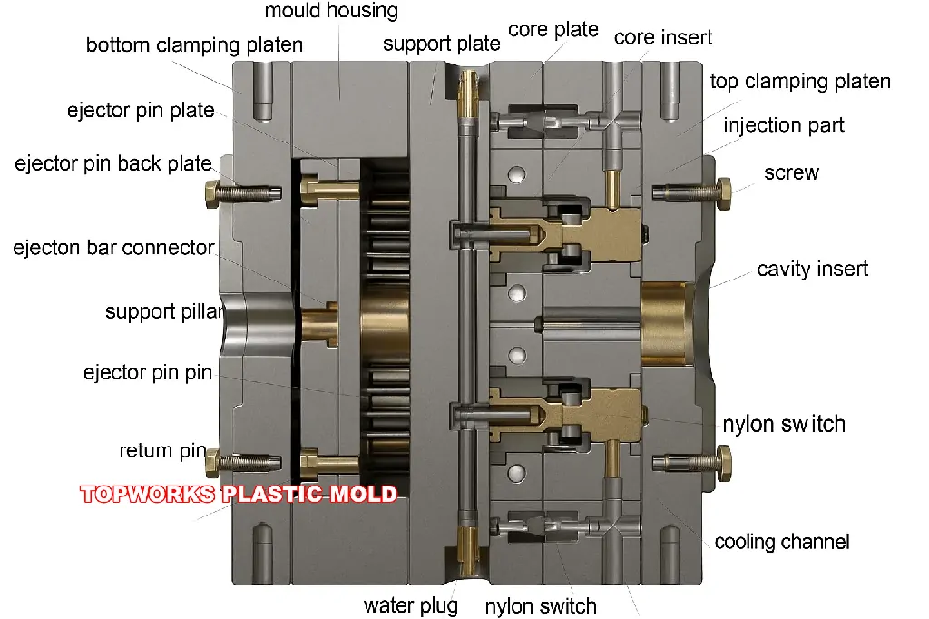
Sélectionnez un composant dans le diagramme ou la liste pour afficher les détails techniques.
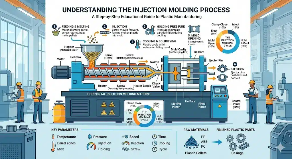
Les six étapes du moulage par injection
- Serrage — Les deux moitiés du moule sont fermées et verrouillées par l'unité de serrage avant le début de l'injection.
- Injection — La résine fondue est injectée dans la cavité du moule à une vitesse et une pression contrôlées.
- Logement (propriété) — La pression de maintien est maintenue afin de compenser le retrait du matériau.
- Refroidissement — La pièce se solidifie à l'intérieur du moule ; le temps de refroidissement dépend de l'épaisseur des parois et de la résine.
- Ouverture du moule — L'unité de serrage se rétracte et les deux moitiés du moule se séparent.
- Éjection — Les goupilles d'éjection poussent la pièce finie hors de la cavité ; le cycle se répète.
Cliquez sur « Exécuter » pour simuler un cycle de moulage par injection de haute précision.
Injection Molding Process Simulator
Adjust parameters with sliders, see real-time effects on part quality and defects
Designing Bosses for Injection Molding
Interactive reference: boss anatomy, a live boss designer, boss types, screw details, defects and material guidelines. Hover or tap any number on the drawings.
| Boss wall t | 0.5–0.6 × T |
| Outer diameter | ≈ 2 × screw d (2.5 × glass-filled) |
| Pilot hole | ≈ 0.8 × d (screw maker's chart) |
| Height H | ≤ 3 × OD; gussets above 2 × OD |
| Draft | 0.5–1° per side, inside and out |
| Base fillet R | 0.25–0.5 × T |
| Thread engagement | 2–2.5 × d |
Why 0.5–0.6 × T? A boss wall as thick as the part wall cools much later than the wall around it; the late-shrinking plastic pulls the show face in (sink) and can leave voids inside.
- →Pilot hole from the screw maker's chart (about 0.8 × d)
- →Engagement 2–2.5 × d; hole deeper than the screw tip
- →0.5 mm chamfer or short counterbore at the entry
- →OD about 2 × d (2.5 × for glass-filled)
- →Hole size and taper from the insert maker's spec
- →Boss OD about 2 × insert OD
- →Hole deeper than the insert so displaced plastic has room
- →Uniform wall around the insert to limit hoop stress
- →Knurls or grooves on the insert for pull-out and torque
- →Pre-heat inserts to cut residual stress
- ✓Keep the boss wall at 50–60% of the nominal wall
- ✓Use gussets or ribs on tall bosses
- ✓Core the boss so it is a tube, not a solid post
- ✓Draft 0.5–1° inside and outside
- ✓Keep bosses away from outside corners
- ✓Radius the base 0.25–0.5 × T
- ✓Tie bosses near a side wall to it with a thin rib
- ✗Make the boss wall as thick as the part wall
- ✗Merge a boss straight into a side wall
- ✗Go above about 3 × OD unsupported
- ✗Leave bosses solid – they always sink
- ✗Space bosses closer than 2 × OD
- ✗Leave a sharp corner at the base
- ✗Skip draft – zero-draft bosses stick and scuff
| Paramètres | Recommandé | Remarques |
|---|---|---|
| Boss wall thickness | 0.5–0.6 × T | T = nominal part wall |
| Boss OD | ≈ 2 × screw d | 2.5 × for glass-filled |
| Pilot hole | ≈ 0.8 × d | Follow the screw maker’s chart |
| Hauteur | ≤ 3 × OD | Gussets above 2 × OD |
| Draft | 0.5–1° per side | Inside and outside |
| Filet de base | 0.25–0.5 × T | Larger radii add mass at the root |
| Thread engagement | 2–2.5 × d | Hole deeper than the screw tip |
| Rib / gusset thickness | 0.5 × T | Thicker ribs sink |
| Boss to side wall | Rib-connected | Do not merge into the wall |
| Boss to boss | ≥ 2 × OD centre to centre | Avoids merged thick sections |
Simulateur de logique de fabrication
Adjust parameters to find the optimal production method.
🔎 How to Use This Calculator
- Select your resin — picks a reference cavity pressure range automatically.
- Adjust cavity pressure — fine-tune based on wall thickness and gate design.
- Set projected area — measure the largest shadow area of one cavity in cm².
- Choose your cavity layout — 1 to 16 cavities, or enter a custom count.
- Read the results — recommended tonnage, machine utilization gauge, and actionable alerts appear instantly.
Clamping Force & Machine Selection
Injection Molding Decision Tools
Estimate your real cost, pick a surface finish, and match the right mold steel. Figures are planning estimates — send a STEP file for an exact quote.
The quote is not the cost. Add duty, freight, and fees to see what a part really lands at.
SPI finish grades, from optical polish to heavy texture. Click a grade to see what it costs you.
Volume, resin, and finish decide the steel. Pick the wrong grade and you pay in rework or a dead tool.
Estimates for planning only. Final cost, finish, and steel depend on part geometry, tolerance, and volume.
1. Sélectionnez le problème que vous souhaitez résoudre
Principaux composants d'un moule d'injection plastique
- Noyau et cavité — donner sa forme à la pièce en plastique.
- Système de coureurs — achemine le plastique fondu dans la cavité.
- Seuil d’injection — point d'entrée par lequel le plastique s'écoule dans la pièce.
- Canaux de refroidissement — Refroidissez le plastique rapidement et uniformément.
- Goupilles d'éjection — extraire la pièce finie du moule.
- Curseur ou élévateur — percer les trous latéraux et les contre-dépouilles.
Cooling & Cycle Time Calculator
Cooling typically accounts for 70%–85% of the injection molding cycle. Cooling time is strongly governed by the square of the thickest wall thickness, making wall design and cooling-system performance critical to productivity and part cost.
Planning estimate based on a 1-D transient conduction, center-temperature model. The bare formula gives the theoretical minimum cooling time; the displayed value adds the chosen safety factor to approximate a real production setpoint. Cooling time follows the approximate wall-thickness-squared relationship, and cooling is typically 70%–85% of the molding cycle. Actual cycle time depends on geometry, material grade, crystallization behavior, mold design, cooling-channel layout, coolant temperature, flow regime, machine settings, and ejection requirements.
Injection Molding Resin Selector
Tell us what the part needs and we rank the common molding resins for you — ABS, PP, PC, PA, POM, PMMA and more — with a side-by-side comparison.
| Matériau | Stiffness | Heat | Impact | Chemical | Coût | Clair | Food | Match |
|---|
Ratings are relative guidance for typical unfilled grades — glass-filled, impact-modified, or specific certified grades differ. Cost ● = higher, ●●●●● = lowest. Confirm food-contact and flammability with the exact grade's datasheet.
Combien coûte un moule d'injection ?
Estimate the one-time tooling cost of an injection mold from part size, cavity count, complexity, and steel — with a China vs. Western price comparison.
This is the one-time tooling cost — not the per-part price.
Get an exact mold quote — send your STEP file →Planning estimate only. A real mold quote depends on part geometry, tolerance, cavity layout, action count, steel, and runner system. Send a 3D file for a firm price.

