
Auto Lamp Mould: The Complete Guide to Types, Materials & Manufacturing
Last updated: 2026
Behind every sharp headlight beam and every glowing tail lamp sits a piece of precision tooling that most buyers never see: the auto lamp mould. It is the single component that decides whether a car light comes out crystal-clear, dimensionally accurate and ready to assemble — or warped, cloudy and full of weld lines.
This guide covers what an auto lamp mould is, the main types, the steel grades and materials that define quality, the step-by-step manufacturing process, the defects that quietly destroy yield, and a practical checklist for choosing a supplier. Whether you are an OEM procurement engineer or sourcing your first tooling partner, you will leave knowing exactly what to specify and what to ask.
What is an auto lamp mould? An auto lamp mould is a precision steel tooling cavity used to injection-mould automotive lighting components — including headlamp lenses (PC/PMMA), reflectors (BMC), housings (PP/ABS) and decorative frames (PBT+GF). It is produced through CNC and EDM machining to tolerances as tight as ±0.005 mm, and a single mould can run from 200,000 to over 1,000,000 shots depending on the steel grade.
What Is an Auto Lamp Mould?
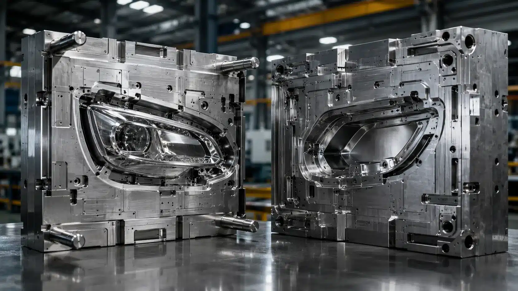
A car lamp is rarely a single moulded part. A typical headlamp assembly combines a transparent lens, a reflector, a lamp housing (body) and one or more decorative frames — and each of these needs its own mould. The auto lamp mould is the tooling that shapes molten plastic (or thermoset compound) into these parts, holds optical-grade surface quality, and repeats that result reliably across hundreds of thousands of cycles.
What separates a lamp mould from an ordinary plastic injection mould is the demand for optical precision. A lens surface must be polished to a mirror finish so light passes through cleanly. A reflector surface must hold near-perfect geometry so the beam pattern meets road-safety regulations. There is little room for the compromises that are acceptable in, say, a battery cover or a bumper clip. For a broader understanding of how injection moulding works at its core, see our overview of plastic injection moulding.
Ready to Get an Accurate Quote?
Topworks combines deep injection molding expertise with structured project management — so your next project lands on time, on spec, and on budget.
Key components of an auto lamp mould
- Core and cavity — the two halves that form the part. The cavity gives the outer (visible) surface; the core forms the inner geometry.
- Cooling system — typically a combination of straight cooling channels (φ8–14 mm diameter, spaced 3–5× the channel diameter apart, positioned 1.5–2× the channel diameter from the cavity surface), baffle inserts for deep cores, and independent circuits for slides. The goal is uniform cavity temperature within ±2.5–5% for semi-crystalline materials and ±5–10% for amorphous materials. See our dedicated guide on injection mould cooling systems for full channel-layout guidance.
- Runner system — cold runner or hot runner channels that deliver melt to the cavity. For lens and housing parts, a point gate (0.8–1.5 mm small parts, 1.5–2.5 mm large parts) or fan gate is common; BMC reflectors use a fan gate because BMC flows poorly. Hot runner systems reduce material waste and allow shorter cycle times but add upfront cost.
- Ejection system — ejector pins, stripper plates, lifters and slides that release the finished part without marking it. The ejection stroke is set to fully clear the part plus an additional 1–2 mm safety margin. Ejector pin locations are placed preferably behind ribs and non-appearance surfaces, distributed symmetrically to avoid one-sided ejection forces.
- Slides and inserts — used heavily in lamp housings, which carry many holes and clips for assembly.
- Venting — vent grooves at the parting line, typically 0.02–0.05 mm deep and 3–12 mm wide, positioned opposite the gate, at the flow front end, and at weld-line convergence zones. Insufficient venting causes gas marks and short shots, especially critical with BMC. Read more about why venting matters in injection moulds.
Auto lamp mould vs a generic plastic injection mould
| Attribute | Generic injection mould | Auto lamp mould |
|---|---|---|
| Surface finish | Standard texture or matte | Mirror polish (to 1000# and finer) for lenses |
| Optical requirement | None | Light transmission & beam-pattern critical |
| Typical materials | ABS, PP, PE | PC, PMMA, BMC, PBT+GF, PA+GF |
| Plating compatibility | Rarely | Frequent (decorative frames are electroplated) |
| Tolerance | ±0.05 mm typical | ±0.005 mm achievable |
| Draft angle | 1–2° general | 0.25–0.5° mirror surfaces; 1–3° textured surfaces |
Types of Auto Lamp Moulds
Identifying the right mould type is the first step in any sourcing conversation. Moulds can be classified three ways: by lamp position, by component, and by moulding technology.
By lamp position
- Headlamp mould — the most complex. Housings carry many lifters, slides and inserts, and the optical surfaces demand the highest finish.
- Tail lamp mould — often produced as a two-colour (2K) mould to combine red and clear zones in a single part.
- Fog lamp mould — simpler geometry and lower precision demand than a headlamp.
- Reading / dome lamp mould — small interior parts with modest tooling requirements.
- High brake lamp (CHMSL) mould — compact, often LED-based.
By component
| Component | Typical material | Steel / hardness | Surface note |
|---|---|---|---|
| Lens | Transparent PC, PMMA | NAK80 or S136, HRC 38–42 / 48–52 | High polish; cavity must never be welded; PC mould temp 80–110 °C |
| Decorative frame | PC, PBT+GF, PA+GF | NAK80 cavity (HRC 38–42); forged steel core | Plating-grade surface required; GF grades: enlarge gate cross-section ~10% |
| Reflector | BMC (thermoset) | 8407 / H13-class steel, cavity HRC 46–50 | Mirror finish; near-zero shrinkage; fan gate essential; heavy venting |
| Lamp body / housing | PP, PC, ABS | P20 (HRC 28–32) or 2738 for large moulds | Many lifters & slides; cooling-critical; PP mould temp 40–60 °C |
By moulding technology
- Single-shot injection — the standard process for most single-material parts.
- 2K / two-colour moulding — injects two materials or colours in sequence using a rotating platen. Essential for tail lamps that blend red and clear zones. The mould uses a rotary or index-plate mechanism to transfer the preform from the first to the second injection station within the same cycle.
- Gas-assisted moulding — used for hollow sections and weight reduction. Our comprehensive guide to gas-assisted injection moulding explains when this process delivers the best results.
- BMC compression moulding — historically used for reflectors, though injection moulding of BMC is increasingly preferred for efficiency and safety.
- Overmoulding — combines a seal and housing in one operation; overmould wall thickness typically ≥0.8–1.0 mm.
Steel Grades & Material Selection
Steel grade is the single biggest driver of both mould quality and price. It determines hardness, polishability, corrosion resistance and — most importantly for production planning — how many shots the mould can run before it wears out. As a general rule, polishability improves significantly with hardness: steels above 40 HRC achieve high-gloss results, while pre-hardened steels around 30 HRC are limited to standard finishes. For a full breakdown of steel options across all mould types, refer to our mould steel selection guide.
Mould steel comparison
| Steel grade | Standard | Hardness | Approx. shot life | Best for | Cost tier |
|---|---|---|---|---|---|
| P20 | 1.2311 | HRC 28–32 | 200,000–300,000 | Prototypes, low volume, housing moulds | $ |
| 2738 (P20+Ni) | — | HRC 30–36 | 300,000+ | Large-section housing moulds | $$ |
| NAK80 | — | HRC 38–42 | 500,000+ | Lens & frame standard; excellent weld-repair | $$ |
| H13 | 1.2344 | HRC 44–50 | 600,000–800,000 | High-volume production; BMC reflectors (8407-class) | $$$ |
| S136 | 1.2083 | HRC 48–52 | 500,000+ | Corrosion-prone optical parts; mirror-finish lenses | $$$ |
| Stavax ESR (stainless) | — | HRC 48–52 | 1,000,000+ | Premium long-run optical tooling | $$$$ |
Rule of thumb: match the steel to the production volume. Specifying stainless tooling for a 50,000-unit run wastes money; specifying P20 for a 500,000-unit run guarantees a costly re-tool halfway through the program.
Surface treatment & polishing
For optical parts, polishing is not cosmetic — it is functional. The typical protocol steps progressively finer: 400# → 800# → 1000# sandpaper, finishing with diamond paste for lens cavities. The relationship between hardness and polishability is direct: steels at 40 HRC achieve good high-gloss results, while those at 50+ HRC enable the finest optical finishes. Fixed moulds are often hard chrome-plated to reduce surface roughness and resist wear. Premium suppliers use vacuum electroslag remelting (ESR) steel for improved crystal uniformity and a superior polishing result — ESR grades have fewer non-metallic inclusions that would otherwise cause pitting and surface inconsistency during polishing. One non-negotiable rule: the reflective (cavity) surface must never be welded, because any weld mark destroys the optical finish. For a reference on surface finish grades and specifications, the Society of Plastics Engineers (SPE) publishes widely-used industry standards on mould surface finish classifications.
Key Design Parameters
Before steel is cut, the design phase establishes the dimensional rules that determine whether a lamp part will demould cleanly, cool uniformly and hold tolerance across hundreds of thousands of cycles. The following parameters are the ones that matter most in auto lamp mould engineering.
Wall thickness
Recommended ranges by material: PC 1.0–3.0 mm (transparent lenses ideally ~2.0 mm); ABS 1.2–3.5 mm; PP 1.2–3.0 mm; PA66+GF 1.5–3.0 mm. Within a single part, wall thickness variation should be kept within ±25% of the nominal thickness to prevent differential shrinkage and sink marks. Our article on how wall thickness and gate placement affect mould cost explores how these decisions ripple through to tooling budget.
Draft angles
General exterior surfaces: 0.5–1°. Deep internal cores: 1–2°. Mirror/high-gloss surfaces: 0.25–0.5° (combined with a robust ejection layout). Textured or grained surfaces: 1–3° depending on texture depth. Rib sides: 0.5–1.5°. Boss outer walls: 0.5–1.5°. For a practical walkthrough of draft angle and wall thickness interactions, see our guide on draft angle and wall thickness in mould design.
Ribs and bosses
Rib thickness: 0.4–0.6× the adjacent wall thickness to prevent sink marks on the opposite face. Rib height: ≤2.5–3× the wall thickness. Rib root radius: R ≈ 0.25–0.4× the wall thickness. Boss outer wall thickness: 0.4–0.6× the surrounding wall; boss root radius R ≈ 0.25× wall thickness.
Gate design
Gate cross-section is typically 3–9% of the runner cross-section. Gate land length: 0.5–1.0 mm for thin-wall parts, 1.0–1.5 mm for thick-wall. Point gate diameter: 0.8–1.5 mm (small parts), 1.5–2.5 mm (large parts). Fan gate thickness: approximately 0.5–0.8× the local wall thickness, width expanding from 4–10 mm upward. For glass-fibre-reinforced grades (PBT+GF, PA+GF), increase the gate cross-section by approximately 10% compared to unfilled grades to reduce shear stress on the fibres. For PC lenses, the preferred gate is a point gate or film gate positioned to push weld lines off the optical zone.
Cooling channel layout
Channel diameter: φ8–10 mm for mid-size lamp moulds, up to φ12–14 mm for large housing moulds. Channel centre-to-cavity surface distance: 1.5–2× the channel diameter (typically 15–20 mm). Channel pitch (centre-to-centre): 3–5× the channel diameter (typically 30–60 mm). Minimum clearance from cooling channels to ejector pins, guide pillars and screw holes: 3–5 mm. Water inlet fittings: positioned at least ~26 mm from the mould edge. For deep cores, use baffle inserts or bubbler tubes to carry cooling water to otherwise unreachable zones.
The Auto Lamp Mould Manufacturing Process
A high-quality lamp mould moves through three broad stages: design, machining, and trial. Understanding each stage helps you read a supplier’s quotation — and spot where corners might get cut.
Step 1 — Design (CAD / CAM / CAE)
- Intake of the customer’s 3D model (STEP/IGES) or reverse engineering from a physical sample.
- CAE simulation (e.g. Moldflow or Cadmould) to predict melt flow, weld-line position, gas traps and warpage before any steel is cut. Weld line strength in the worst case can be as low as 20% of the unwelded material strength — simulation lets you relocate weld lines off structurally or optically critical zones before committing to steel. Our in-depth article on when Moldflow analysis is mandatory and when to skip it helps you decide where simulation investment pays off.
- Parting line design — placed at natural geometric breaks where possible; appearance surfaces and sealing grooves must be kept clear of the parting line.
- Gate design tailored to material: a fan gate for poor-flowing BMC, a point gate or film gate for transparent lenses. Gate location determines weld-line position, so it is optimised in simulation first.
- Venting layout: vent grooves (0.02–0.05 mm depth, 3–12 mm wide) positioned opposite the gate and at every predicted flow-front convergence zone.
Step 2 — Machining (CNC + EDM)
Two core processes shape the mould:
| Process | Use | Typical precision |
|---|---|---|
| 5-axis CNC | Bulk cavity & core geometry | ±0.005 mm |
| Wire-cut EDM | Insert pins, complex profiles, precise contours | ±0.002 mm (±2 μm); Ra achievable to 0.2 μm with finish passes |
| Sink (die-sinking) EDM | Optical textures and fine detail CNC cannot reach | ±0.003 mm (±3 μm) maximum |
EDM (Electrical Discharge Machining) removes material with rapid electrical sparks between an electrode and the workpiece without physical contact — temperatures in the plasma channel reach up to 40,000 K, eroding material in a controlled crater pattern. This is why EDM can produce the fine, complex detail that lamp optics demand. Wire-cut EDM uses a brass wire of 0.20–0.25 mm diameter, calibrated to 1 μm, running fully automatically. Sink EDM electrodes for lamp optics are typically copper for small features and graphite for large cavity sections.
Step 3 — Assembly, trial run & sampling
- Mould assembly and first-shot (T1) sampling.
- Evaluation of appearance, dimensions and assembly fit against the customer specification. Part-body tolerances typically fall in the ±0.05–±0.25 mm range; critical mating features and insert fits are held to ±0.01–±0.05 mm.
- Comparison of actual results to the CAE prediction; defect correction over typically one to three iterations.
- Light-uniformity verification — leading manufacturers target above 98%, well beyond the industry baseline.
- Process window validation: confirm that key material parameters are within specification — for example, PC lenses require a mould temperature of 80–110 °C and a melt temperature of 280–320 °C; ABS housings run at 45–80 °C mould temperature and 190–235 °C melt temperature.
Common Defects & How to Prevent Them
Most lamp mould failures are predictable — and preventable at the design stage. These are the three that cause the most scrap. For a wider catalogue of moulding defects and their root causes, our analysis of injection moulding defects and resolutions is a useful companion reference.
Adhesive mould (part sticking)
Lamp housings are especially prone to sticking. Prevention starts in part design: keep wall thickness variation within ±25% of nominal to avoid differential shrinkage, apply adequate draft angles (minimum 0.5–1° on plain surfaces, 1–2° on deep cores), and design a robust ejection system with symmetrically distributed ejector pins placed behind ribs and bosses. For large flat areas, a stripper plate is preferred over pin ejection. Ejection stroke must fully clear the part and travel an additional 1–2 mm beyond that point.
Weld lines & gas marks
Weld lines form where two melt fronts meet; their strength can be as low as 20–80% of the base material depending on process conditions. Push them off appearance surfaces by optimising gate location in simulation, and design proper venting (0.02–0.05 mm depth) to release trapped gas — a frequent problem with BMC reflectors. Short-shot balance testing in multi-cavity moulds (filling to ~90–95% and measuring cavity-to-cavity variation) can identify flow imbalances before full production.
Warpage & deformation
Uneven cooling is the usual culprit. The proven answer is a balanced cooling layout — equal-pitch channels surrounding the cavity at 1.5–2× the channel diameter from the cavity surface, with independent circuits for slides and deep cores — to deliver uniform, assembly-ready flatness. Cooling water inlet-to-outlet temperature difference should be kept to 2–4°C (maximum 5°C); a larger ΔT indicates uneven heat extraction. Where shrinkage is predictable, geometry can be pre-compensated in the mould itself. Our case studies on injection mould deformation defects show how these principles are applied to real production problems.
How to Choose an Auto Lamp Mould Supplier
Sourcing tooling is a high-stakes decision: a poor mould can sink a product launch. Use this checklist to qualify any supplier before placing an order. For broader guidance on evaluating Chinese tooling partners, our article on choosing the right injection moulding manufacturer in China covers the full qualification process, and the AIAG automotive core quality tools (including APQP and PPAP) provide the industry-standard framework that serious automotive suppliers follow.
Technical capability
- 5-axis CNC machining in-house
- In-house EDM (both wire-cut and sink)
- CAE simulation software (Moldflow, Cadmould or equivalent)
- CMM measurement and a documented dimensional inspection report
- A clean, controlled environment for polishing optical surfaces
- Proven experience with 2K tooling for tail lamp applications
Quality & certification signals
- IATF 16949 — the automotive quality-management standard; the strongest single signal. The IATF Global Oversight website allows you to verify a supplier’s certification status directly.
- ISO 9001 — the minimum baseline.
- Named OEM references (Ford, Toyota, BAIC, SGMW and similar) — verifiable social proof.
- Willingness to share T1 sampling reports openly.
Commercial terms to benchmark
- Lead time: roughly 45–90 days is normal (commonly around 20 days for design analysis and 60 days for production).
- Warranty: one year of free service plus lifetime maintenance is a competitive norm.
- MOQ: from a single set for fully custom tooling up to 10 sets for standardised moulds.
Auto Lamp Mould Cost Factors
There is no flat price for a lamp mould — the quotation reflects a stack of design decisions. The biggest cost drivers are:
- Steel grade — moving from P20 to Stavax ESR can multiply tooling cost two to three times, but extends shot life from ~250,000 to over 1,000,000 cycles.
- Number of cavities — a multi-cavity mould costs more upfront but lowers per-part cost at volume.
- Part complexity — every slide, lifter, insert and EDM electrode adds cost. Lamp housing moulds with many clips and snap features require significantly more slides than a simple lens mould.
- Surface finish level — standard vs mirror vs plating-grade. Mirror polishing of optical cavities requires premium ESR steel and skilled manual finishing work.
- Runner system — hot runner costs more than cold runner but reduces material waste and often shortens cycle time, improving economics at high volume.
To control cost without sacrificing quality, insist on an early DFM (Design for Manufacturability) review to avoid re-machining, consider P20 tooling for prototypes before committing to H13 or S136 for production, and use standardised mould bases (LKM, HASCO, DME) where possible. Our comprehensive guide to mastering injection moulding costs walks through each cost lever in detail.
Frequently Asked Questions
What is an auto lamp mould used for?
It is used to injection-mould automotive lighting components — headlamp lenses, reflectors, housings, decorative frames, fog lamps and tail lamps — at high volume and optical-grade quality.
What steel is used for automotive lamp moulds?
Common grades include P20 (HRC 28–32) for prototypes and housing moulds, NAK80 (HRC 38–42) for lenses and frames where weld repair is needed, H13/8407-class (HRC 44–50) for high-volume and BMC reflector applications, S136 (HRC 48–52) for corrosion-resistant optical parts, and Stavax ESR (HRC 48–52) for premium long-run tooling exceeding one million shots.
How long does an auto lamp mould last?
Shot life depends on steel grade: roughly 200,000–300,000 shots for pre-hardened P20, 600,000–800,000 for heat-treated H13, and over 1,000,000 for stainless Stavax ESR tooling under ideal conditions.
What is a 2K auto lamp mould?
A 2K (two-colour) mould injects two materials or colours into one part in sequence, using a rotating platen or index plate to transfer the preform between injection stations. It is widely used for tail lamps that combine red and clear zones in a single moulded piece.
What is BMC in lamp mould reflectors?
BMC (Bulk Moulding Compound) is a thermosetting plastic with near-zero shrinkage, high heat resistance and flame retardancy — ideal for reflectors, which is why it is paired with 8407-class steel (H13-type) polished to a mirror finish. Because BMC flows poorly, a fan gate is standard, and venting must be generous to evacuate the gas generated during curing.
How long does it take to manufacture an auto lamp mould?
A typical timeline is 45–90 days: often around 20 days for design and analysis followed by roughly 60 days for machining, assembly and sampling.
What draft angle is required for lamp mould surfaces?
Mirror-finish and high-gloss optical surfaces require a minimum draft of 0.25–0.5°. General exterior surfaces use 0.5–1°, deep internal cores 1–2°, and textured or grained surfaces 1–3° depending on texture depth. Insufficient draft is one of the most common causes of part sticking in lamp housings.
Conclusion
An auto lamp mould is a precision optical tool, not a generic plastic die — and treating it that way is what separates a clean product launch from an expensive re-tool. Match your steel grade to your production volume (P20 for prototypes, NAK80 or S136 for optical parts, H13 for volume production), insist on CAE simulation before any steel is cut, demand transparent T1 sampling reports, and qualify your supplier against the IATF 16949 standard. Get those four things right and the mould will quietly do its job for hundreds of thousands of cycles.
Need a lamp mould for a specific lamp type? Request a free DFM analysis of your design, or download our 25-point supplier audit checklist before you place an order.

