
DFM & Material Science
Plastic Shrinkage Guidelines in Injection Molding Design
Every polymer contracts as it cools from molten processing temperatures down to ambient room temperature. Accurately compensating for plastic shrinkage in part CAD and cavity steel sizing prevents warpage, sink marks, shrink voids, and out-of-tolerance dimensions.
- Semi-Crystalline Thermoplastics (HDPE, PP, POM, PA): Shrink 1.5% to 2.5% (up to 0.050 in./in. for polyethylene) as polymer chains fold into dense crystalline lattices.
- Amorphous Thermoplastics (ABS, PC, PMMA): Shrink 0.4% to 0.7% due to random molecular structure with zero crystallization.
- Thermosets (Phenolic, Epoxy, Silicone): Phenolic resins shrink 0.001 to 0.015 in./in.; hot-cured epoxies and silicones can contract upwards of 5%.
- Mold Temperature Baseline: Start general tooling trials at a mold surface temperature of 60–80°C and tune packing pressure where sink marks appear.
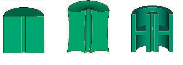
Plastic shrinkage is the dimensional contraction of a molded part as it cools inside the cavity and relaxes after ejection. Because each polymer family has distinct thermal expansion and crystallization behavior, toolmakers machine specific shrink factors into the steel cavity so the cooled part hits nominal print dimensions.
Uncontrolled shrinkage causes four major injection molding defects: warpage, sink marks, internal voids, and undersized features. Minimizing these defects requires balancing resin selection, press process parameters, and cooling channel geometry.
What Causes Plastic Shrinkage in Injection Molding?
Plastic shrinkage occurs because molten polymers expand under thermal energy in the barrel and contract as heat transfers into the mold steel. Linear shrinkage is calculated from the dimensional difference between the cold mold cavity and the stabilized molded part at room temperature.
Material family dictates the baseline contraction range. A thermosetting phenolic resin shrinks between 0.001 and 0.015 in./in. depending on filler ratio, mold steel grade, and curing pressure. By contrast, semi-crystalline thermoplastics such as polyethylene can shrink up to 0.050 in./in. Predicting exact local shrinkage across varying wall thicknesses requires analyzing how six material and machine variables interact:
| Polymer Category / Variable | Typical Linear Shrinkage / Setting | Shrinkage Mechanism & Tooling Impact |
|---|---|---|
| Semi-Crystalline (HDPE, PP, POM, PA) | 1.5% – 2.5% (up to 0.050 in./in.) | Chains fold into tight crystal structures during cooling; high anisotropic shrinkage risk. |
| Amorphous (ABS, PC, PMMA) | 0.4% – 0.7% | Random chain orientation without crystallization; tighter dimensional stability. |
| Phenolic (Thermoset) | 0.001 – 0.015 in./in. | Controlled by compound formulation, mold material, and compression/transfer conditions. |
| Epoxy & Silicone (Thermoset) | Upwards of 5.0% | High thermal contraction from hot curing state down to room temperature. |
| Glass Fiber / Mineral Fillers | Reduces base shrink by 30%–60% | Rigid fibers constrain longitudinal contraction but create directional shrink differences. |
The Type of Plastic
Semi-crystalline plastics like HDPE, PP, POM, and PA shrink between 1.5% and 2.5%, which is more than three times the contraction of amorphous plastics like ABS, PC, and PMMA (0.4% to 0.7%). Thermosets like epoxy and silicone can shrink upwards of 5% when cooling from curing temperatures to room temperature. Adding high filler loadings and glass fiber reinforcements physically constrains polymer chain contraction.
The Melt Temperature
Higher melt temperatures lower resin viscosity and increase thermal expansion inside the barrel. As the superheated melt cools and crystallizes inside the cavity, total volumetric contraction increases. Process engineers must balance easy cavity filling against excessive heat history.
The Mold Temperature
Low mold temperatures freeze the outer plastic skin rapidly, restricting uniform packing and locking in residual thermal stresses. Excessively high mold temperatures allow fuller crystallization—increasing total shrinkage—and extend overall cycle time. Run the highest mold temperature that preserves dimensional stability without penalizing cycle economics.
The Injection Pressure
Higher injection pressures drive melt into the cavity with greater momentum, stretching polymer chains along the flow path. As the part cools, oriented molecules recoil and relax, creating directional shrinkage differences between the flow and cross-flow axes.
The Packing Pressure
Raising packing pressure and holding time forces additional resin into the cavity as the core cools, pressing the part walls firmly against the steel. Proper packing prevents sink marks over thick ribs, though over-packing locks high residual stress around the gate.
The Cooling Time
Rapid cooling freezes polymer chains in an expanded state before full relaxation occurs, whereas gradual cooling permits uniform contraction and stress relief. Set cooling time long enough to achieve dimensional stability below the heat deflection temperature without starving press productivity.
Tips for Controlling Plastic Shrinkage in Injection Molding
Controlling plastic shrinkage requires combining uniform mold thermal management with repeatable press settings and DFM geometry adjustments:
Use a Mold with a Conformal Cooling Cavity
Conformal cooling channels follow the exact 3D contour of the mold core and cavity to extract heat evenly across complex geometries. Eliminating hot spots prevents localized differential shrinkage that twists parts out of flat. Toolmakers manufacture conformal cooling inserts using direct metal laser sintering (3D printing) or CNC-machined beryllium copper (BeCu) sub-inserts.
Increase the Melt Temperature
Running a moderately higher melt temperature drops polymer viscosity so packing pressure can transmit further toward the end of fill. Improved pressure transmission packs out remote walls and reduces flow-induced orientation stress, provided barrel temperatures stay below the resin degradation limit.
Lower the Mold Temperature
Cooler cavity surfaces freeze the outer skin faster to lock part geometry early, though overly cold steel causes flow lines, incomplete packing, and post-mold warpage. For general thermoplastic trials, start with a baseline mold temperature between 60°C and 80°C and adjust according to the resin datasheet.
Increase Injection Pressure
Faster, higher-pressure injection fills thin cavity sections before viscosity rises from premature cooling. Adequate fill pressure eliminates micro-voids, provided shear rates at the gate stay within safe limits to avoid molecular orientation.
Optimize Packing Pressure and Time
Applying sustained packing pressure until the gate freezes compensates for volumetric contraction as the core solidifies. Increase holding pressure incrementally only until visible sink marks disappear and part weight stabilizes.
Allow Sufficient Cooling Time
Thick-walled sections require extended cooling time so the internal core crystallizes and contracts evenly before mold opening. Ejecting a part before its core drops below the resin heat deflection temperature causes immediate post-ejection warping.
Maintain a Consistent Process
Shot-to-shot fluctuations in melt temperature, hydraulic pressure, or water flow rate translate directly into dimensional scatter. Install cavity pressure transducers and closed-loop process controllers to detect viscosity drift and adjust pack profiles automatically.
Account for Shrinkage in Part and Mold Design
Apply the correct shrinkage factor to the 3D CAD model before cutting steel, and follow DFM rules: maintain uniform wall thickness, add structural ribs and draft angles, core out heavy bosses, and apply surface texturing to mask minor sink marks.
The Impact of Plastic Shrinkage on Part Quality
Uncompensated plastic shrinkage causes four structural and cosmetic failure modes in production parts:
- Warpage — Differential shrinkage across uneven wall thicknesses or unbalanced cooling circuits bends and twists the part after ejection.
- Sink Marks — Surface depressions form over thick bosses, heavy ribs, and internal inserts when the outer skin pulls inward toward a shrinking, under-packed core.
- Cracks and Voids — Internal vacuum bubbles (shrink voids) or surface stress cracks form when the outer shell freezes rigid while the molten center contracts without sufficient packing feed.
- Poor Dimensions — Miscalculating the steel shrink factor produces undersized parts that fail assembly stack-up tolerances.
Delivering dimensionally accurate parts requires matching resin shrink data with Moldflow simulation, uniform cooling layouts, and gate-freeze packing studies before authorizing multi-cavity production tooling.
Need help calculating steel shrink factors or fixing warpage on a tight-tolerance part? Upload your 3D CAD file for an engineering DFM analysis.

