
DFM CASE STUDY · POLYCARBONATE ENCLOSURE · 2-PLATE MOLD
DFM Case Study: How We Redesigned a Polycarbonate Enclosure for a 1×2 Injection Mold
Every polycarbonate enclosure looks simple on the customer’s drawing. Uniform walls. Clean corners. A snap-fit lid and four bosses. Then the DFM report comes back and the “simple” part turns into a conversation about corner radii, ejector pin marks, insert lines, and how much your customer is willing to tolerate on the visible A-surface.
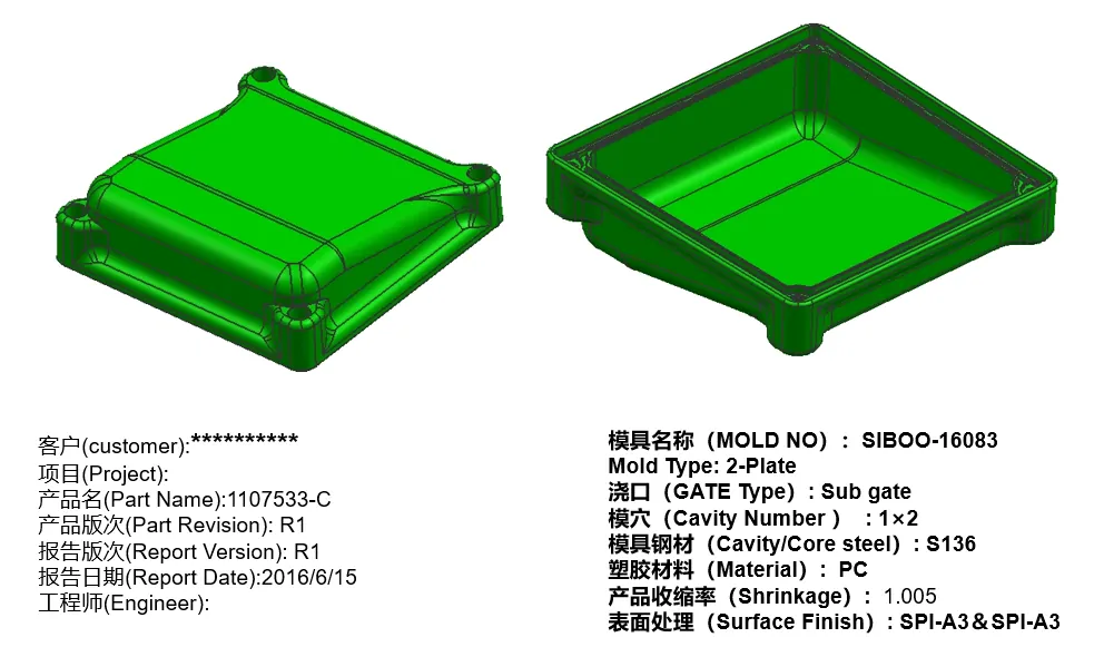
This case study walks through a real DFM we completed on part number 1107533-C, a 2-cavity PC enclosure tooled on our internal reference Siboo-16083. Instead of showing the finished mold and calling it a success story, we want to show what the DFM report actually flagged, why each flag matters at the mold-flow and cost level, and what the customer agreed to change before we cut steel.
Design for Injection Molding
Eight checks that decide whether your part molds clean, or fights the tool for its whole life.
Wall thickness rules the whole job
Wall thickness sets cycle time, sink marks, warpage and fill pressure. Cooling time rises with the square of the wall. Double the wall and you roughly quadruple the time the part sits in the tool.
The second rule matters just as much: keep the wall uniform. Plastic shrinks as it cools. A thick zone cools last, keeps shrinking after the gate freezes, and pulls the surface in. That is a sink mark. If the skin is stiff enough to resist, the shrinkage tears a void inside instead.
Hold the nominal wall within ±10% across the part. Where a change is unavoidable, keep the step under 25% of the nominal wall and blend it over a length of at least 3× wall. Never step the wall with a square shoulder.
Cooling time is a first-order estimate from the one-dimensional plate solution. It ignores gate freeze-off, hot runner effects and mold cooling layout. Treat it as a comparison tool, not a quote.
Stiffness comes from ribs, not from thicker walls
Bending stiffness scales with height cubed. A rib 3× the wall height adds far more stiffness than doubling the wall, and it costs almost nothing in cycle time. This is the single highest-value move in plastic part design.
The catch is the rib root. Where the rib meets the wall, material mass builds up. That local thick spot cools last and pulls a sink mark onto the show surface directly opposite the rib.
Base thickness 0.5–0.6× wall for amorphous resins, 0.4–0.5× for high-shrink semi-crystallines. Height up to 3× wall. Draft 0.5–1.5° per side. Root radius 0.25–0.5× wall. Spacing at least 2× wall so the steel between ribs still cools.
Three fixes, in order of cost: move the rib off the show face, break the opposite face with a texture or a styling groove, or core out the wall behind the rib so the mass balances. Adding hold pressure only hides small sinks and often adds stress instead.
Draft is what lets the part leave the steel
A molded part shrinks onto the core. Ejector pins then push it off. With no taper, the part drags the full depth of the core and picks up scuff lines, stress whitening or a torn wall. Draft turns that sliding contact into an instant release.
Texture makes it worse. A grained surface is a field of tiny undercuts. Every 0.025 mm of texture depth needs roughly 1.5° of extra draft on top of the base requirement.
0.5° is the practical floor for a polished vertical face. 1–2° is the normal default. 3° suits a light grain, 5° and up a coarse one. Deep ribs and tall cores want at least 0.5° per side even when the drawing says the face is critical. Shut-off faces and sealing surfaces are the exception, and they need a written agreement before steel is cut.
Sharp inside corners are stress risers
A sharp internal corner concentrates stress, blocks flow and creates a local hot spot in the steel. It is also the place parts break first in drop tests. Adding a radius is free at the design stage and expensive after the tool is cut.
The chart below is the classic stress-concentration curve. Below R/T = 0.3 the factor climbs steeply. Above R/T = 0.6 you gain almost nothing, and you start adding mass that sinks.
Outside radius = inside radius + wall thickness. Do that and the material thickness through the corner stays equal to the nominal wall. Use the same inside radius everywhere so the polisher runs one ball cutter, not five.
Bosses: strong enough to hold a screw, thin enough not to sink
A boss is a rib rolled into a tube. Every rib rule still applies, plus two more. The wall of the boss has to stay thin relative to the nominal wall, and the boss must not sit directly against a side wall, or the two masses merge into one thick lump.
Core the boss from the parting line so the wall stays even. Give the core 0.25–0.5° draft, or it will not release. Stand the boss off the side wall by at least one wall thickness and tie it back with a gusset. Keep thread engagement at 2–2.5× the screw diameter, and add a counterbore at the mouth so the screw starts straight and the top of the boss does not split.
Every undercut buys a moving part in the tool
The cheapest mold opens in one direction and the part falls out. Anything that traps the part needs a slide, a lifter, a collapsible core or an unscrewing unit. Each one adds cost, adds cycle time, adds a witness line on the part, and adds something that can fail at 200,000 shots.
Pick the features your part actually needs. The panel adds up what they do to the tool.
Many undercuts disappear with a small change. Add a pass-through hole in the opposite face so a core pin can form the feature on straight pull. Move the parting line onto a styling break. Split one part into two and weld or clip them. Turn a rigid snap into a shallow bump-off that a flexible resin can strip over. Each of these is worth an hour of CAD work before the RFQ.
The gate decides where the weak lines land
Melt enters at the gate and races outward. Where two flow fronts meet, they form a weld line. That line can be 20–60% weaker than the bulk material, and on a glass-filled resin it is worse, because the fibers lie parallel to the line instead of across it.
Click anywhere in the plate to move the gate and watch the fill pattern change. Openings split the flow and put a weld line downstream of every hole.
Click the plate to place the gate.
Choosing a gate type
| Gate | Auto de-gate | Vestige | Best for | Watch out for |
|---|---|---|---|---|
| Edge / side | No | Trimmed nub | Flat parts, most tooling | Manual trim adds labor |
| Submarine (tunnel) | Yes | Pin mark, hidden | Small to medium parts | High shear, not for filled or brittle resins |
| Hot tip / valve gate | Yes | Small dimple or flat | Cosmetic parts, no runner scrap | Highest tool cost, needs controller |
| Direct sprue | No | Large scar | Thick single-cavity parts | Sink under the gate, long cooling |
| Fan | No | Wide trimmed edge | Wide flat panels, low warp | Needs trim fixture |
| Diaphragm | No | Ring on the bore | Round parts needing concentricity | Secondary machining |
Where can a gate vestige be accepted? Which surface is cosmetic, so the weld line must be moved off it? Is the longest flow path within reach for this resin at this wall? Answer those and the filling analysis usually confirms what you already chose.
Shrinkage first, tolerance second
The cavity is cut larger than the part. How much larger depends on the resin, the wall, the hold pressure and the direction of flow. Semi-crystalline resins shrink two to four times more than amorphous ones, and glass fiber makes shrinkage directional.
That is why a tolerance that is routine in aluminum can be impossible in PP. Ask for tight numbers only where the function needs them, and say which datum they are measured from.
Hold pressure and hold time change shrinkage more than any other setting. Mold temperature comes next, then wall thickness. A part measured hot off the press is not the part you get 48 hours later, especially in PA and POM. Set your inspection window and write it on the drawing.
Values shown follow the general shape of the SPI and DIN 16742 guidance for standard and fine tolerance grades. Use them to sanity-check a drawing early. A final capability statement comes from the mold flow study and the first-article report.
Self-check
Eight questions from the sections above. Answers explain themselves as you go.
- Part: 1107533-C, PC enclosure (upper + lower shell style)
- Mold No.: SIBOO-16083
- Mold type: 2-plate
- Cavity number: 1×2 (family, upper + lower in one mold)
- Cavity/core steel: S136
- Resin: SABIC LEXAN™ ML945 PC (UL 94 V-0, non-halogenated FR)
- Shrinkage: 1.005
- Gate: Submarine (sub) gate
- Surface finish: SPI-A3 exterior / SPI-B3 interior
Why we run a formal DFM before quoting a mold
A DFM (Design for Manufacturability) report is not paperwork. It is the last chance to make cheap changes. Once we cut S136, every geometry change becomes a weld repair, a slide re-machine, or a full insert swap. On a 1×2 PC enclosure like this one, we typically catch three to seven issues at the DFM stage. Most of them are worth 200 to 2000 USD in avoided rework and one to three weeks of avoided schedule slip.
For this project the DFM produced four material findings and three process recommendations. We cover each below in the order they appeared in the report, with the mold-flow reasoning behind them.
1. Wall thickness inspection — the corner R was too large
The first check on any PC part is uniform wall thickness. PC shrinks between 0.5% and 0.7% and does it slowly, so any thick section pulls material away from thinner neighbors during cooling. That is the mechanism behind sink marks and internal voids.
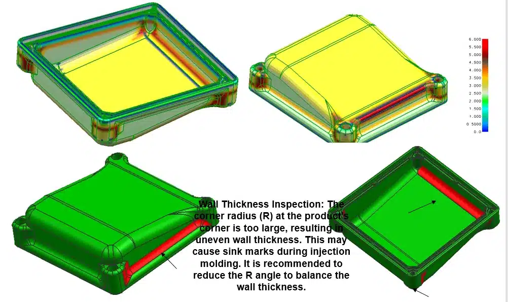
Our wall thickness scan on 1107533-C showed the flat top and sidewalls sitting in a healthy 2.0 to 2.5 mm range, colored green in the analysis. The four corner fillets, however, showed up bright red — the corner radius (R) the customer had drawn was so generous that the corner region measured 5 to 6 mm thick. That is more than double the nominal wall.
A 5 mm corner next to a 2.5 mm wall cools at roughly one-quarter the rate. By the time the thin wall is solid and dimensionally locked, the thick corner is still contracting. The contraction has to go somewhere — either inward as a visible sink mark on the outside of the corner, or as an internal void you will only discover at qualification. On SPI-A3 finished PC, either outcome is a scrap part.
Our recommendation was to reduce the external corner radius and, more importantly, to core out the inside of the corner so that the wall thickness measured through the corner matched the nominal 2.5 mm ± 10%. The customer accepted the change on the 3D revision before tooling started. This is the single most expensive fix to make after steel is cut, and one of the easiest to make at DFM.
2. Draft angle inspection — passed, but worth explaining
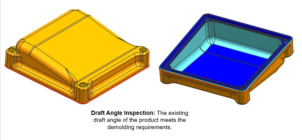
The draft check came back clean. The existing angles on both cavity and core sides were sufficient for the SPI-A3 exterior and SPI-B3 interior finish combination we planned to use.
This one is worth spending a paragraph on, because a lot of buyers think “if the CAD looks vertical, we can polish it out later.” You cannot. Draft angle requirement scales with surface finish. A smoother mold surface grabs the plastic harder during ejection. Rough industry rule (aligned with published design-for-molding guidance from Plastics Technology):
| Mold surface finish | Minimum draft we recommend on PC |
|---|---|
| SPI-A1 / A2 (high-polish, optical) | 1.5° to 2° |
| SPI-A3 (fine polish, our exterior spec here) | 1° to 1.5° |
| SPI-B1 / B2 (paper polish) | 0.5° to 1° |
| SPI-B3 / C (fine stone, our interior spec) | 0.5° |
| Textured (VDI or MT) | 1° per 0.025 mm of texture depth |
The customer’s original geometry cleared these numbers on every relevant face. No change needed. We noted it in the report anyway, because the customer’s next revision could easily break the draft budget without them realizing it.
3. Ejection layout — 4 sleeve ejectors + 4 blade ejectors
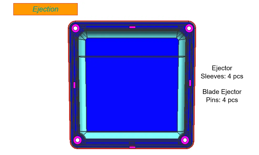
PC enclosures with tall sidewalls and small internal ribs are notorious for two ejection problems: white marks on the four corner bosses (from sleeve or pin push), and drag marks along the ribs (from the ribs sticking to the core steel).
Our layout for this mold used four ejector sleeves — one under each corner boss — and four blade ejectors for the small internal support ribs on the sidewalls. Sleeves are the right choice under bosses because they push on the annular face around the boss hole rather than on the boss face itself, so any push-back witness is hidden inside the mounting hole. Blades are the right choice on thin ribs because a round ejector pin under a thin rib will either miss the rib or leave a huge circular witness larger than the rib itself.
We asked the customer to remove the small radius (fillet) at the base of the four internal ribs where they meet the sidewall. The reason is not stress concentration — on a non-structural enclosure that fillet does nothing useful. The reason is that a fillet at the base of a rib forces the ejector to be either round (leaving a witness larger than the rib) or set back from the rib (leaving the rib un-ejected). Removing the fillet lets us drop a blade ejector flush with the rib footprint. No witness on the outside of the wall, clean rib ejection.
4. Surface finish specification — SPI-A3 exterior, SPI-B3 interior
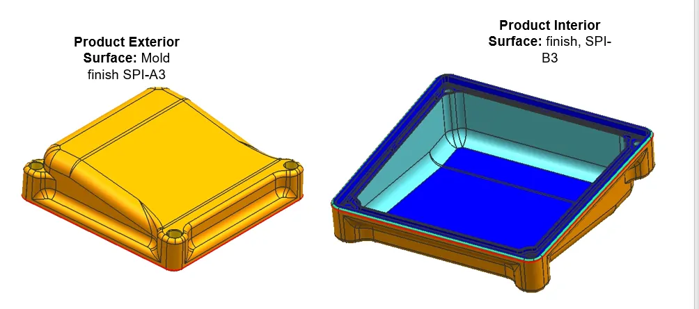
Splitting exterior and interior finish is the cost-conscious call on a consumer-facing enclosure. The customer sees the outside, so it gets the A-series polish. The inside gets a fine-stone SPI-B3 finish, which is enough to prevent sticking and drag but avoids the labor cost of full polish where nobody will ever look. For a deeper primer on the SPI mold surface finish grades, see our reference guide.
There is a hidden reason to run B3 on the inside: it forgives the ejection witnesses. Any blade or pin push mark on a B3 surface reads as texture, not defect. On a mirror A1 interior, the same mark reads as a scrap trigger.
We flagged one item in the report — the interior floor of the enclosure is visible when the lid is off, so we asked the customer to confirm B3 was acceptable there specifically. It was.
5. Insert construction on the through-holes — expect visible parting lines
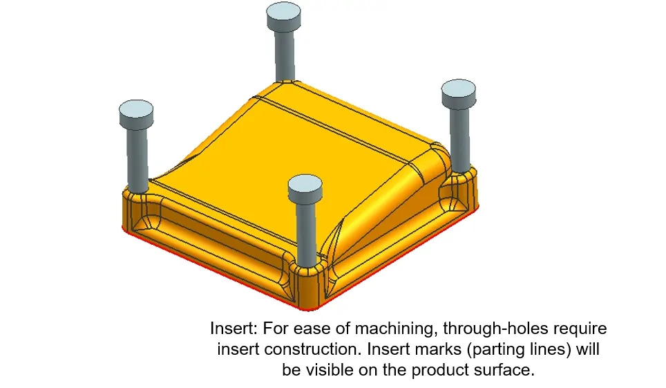
The four corner bosses on this part are through-holes designed to accept M3 mounting screws. On a 1×2 mold in S136, machining these holes as a single-piece cavity is possible but expensive — you would need to sink EDM the boss ID with a small electrode and manage the taper carefully.
The standard cost-effective approach is to build the boss as an insert. A cylindrical insert is machined separately on a lathe, then pressed into a socket in the cavity. Cheaper to make, cheaper to replace when it wears, and easier to re-polish independently of the main cavity.
The trade-off is that every insert creates a parting line on the molded part where the insert meets the cavity steel. On this geometry, that means four visible ring witnesses around each of the four boss tops. We showed the customer exactly where these lines would appear in the DFM report and got sign-off before proceeding. The alternative — hiding the parting line by machining the boss into the main cavity — added about 800 USD to the tooling cost and two extra days of EDM time. The customer picked inserts.
6. Gating strategy — submarine gate with automatic degating
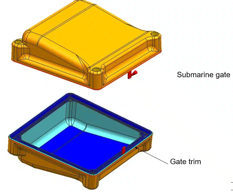
Sub gate (also called submarine gate or tunnel gate) was our recommendation and the customer’s original spec, so this was more of a confirmation than a decision. If you want the wider context on where and why to set gates in injection molding, we cover the trade-offs in more detail there.
The reason to use a submarine gate on a family mold like this one is automatic gate separation at ejection. The gate is cut into the parting line at an angle, so as the mold opens, the gate is sheared off cleanly by the parting motion. No secondary trimming operation. On a 1×2 family mold that will produce hundreds of thousands of sets, saving the trim operation compounds fast.
- Melt enters through the sprue and runs down the cold runner
- At each cavity, the runner turns into a tapered tunnel that pierces the parting line and enters the cavity below the parting surface
- Melt fills the cavity; gate freezes off
- Mold opens; the tunnel geometry and the ejection motion combine to snap the gate at its narrowest point
- Runner and gate leave with the runner, part leaves with the cavity, no trimming needed
The gate location we chose puts the vestige on an internal wall of the lower shell where it is not visible in the assembled product. The gate trim mark is inside the enclosure.
7. Parting line — standard flat P/L on both parts
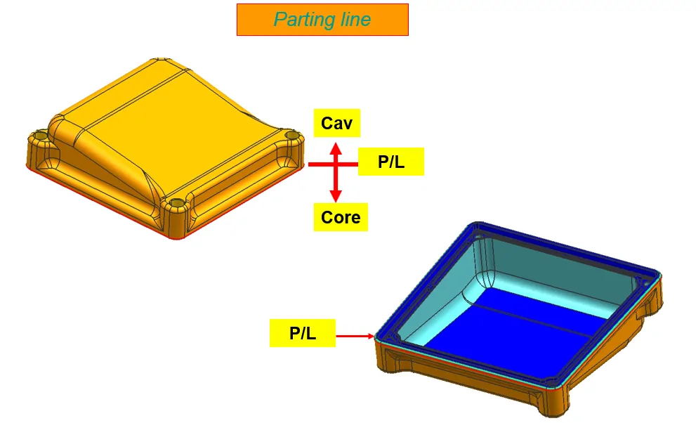
The parting line for both the upper and lower shells sits at the top of the sidewall, dividing cavity (top, exterior) from core (bottom, interior). This is the textbook layout for a shallow shell part and it gives us three benefits:
- The A-surface (exterior) sits entirely on one side of the parting line, so the SPI-A3 polish is uninterrupted by any parting witness on the visible face
- All the ejection hardware sits under the interior, on the core side, where the B3 finish absorbs witnesses
- Sub gate integration at the P/L is straightforward, without requiring a three-plate or hot runner setup
No changes requested. This is what a boring, uneventful parting line section of a DFM report looks like, which is exactly what you want.
Material selection notes — SABIC LEXAN ML945
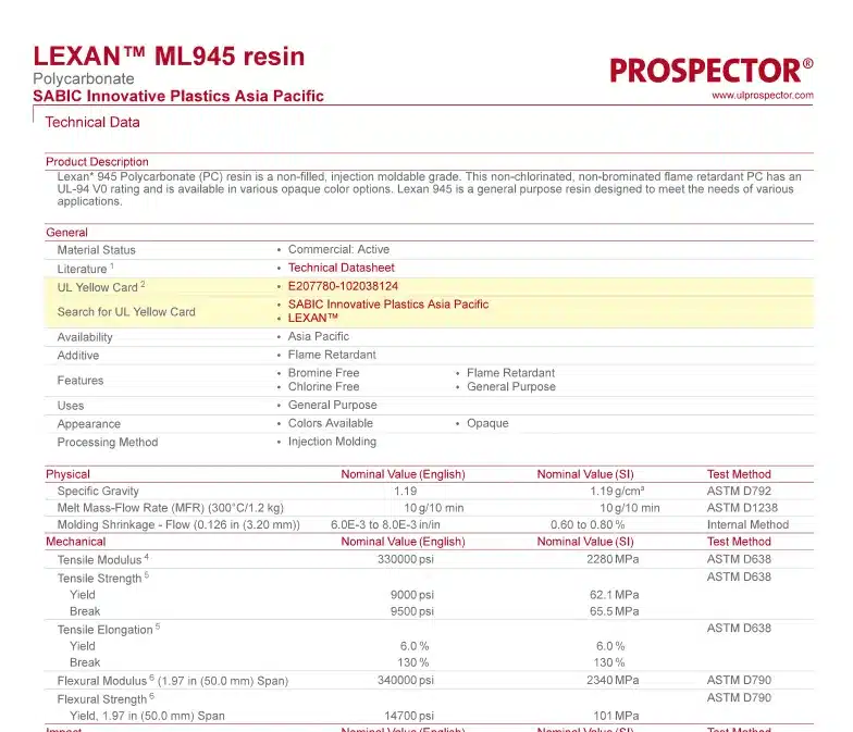
The customer specified LEXAN ML945, a general-purpose polycarbonate from SABIC’s Asia-Pacific portfolio. It is a non-chlorinated, non-brominated flame-retardant PC with a UL 94 V-0 rating. For a broader treatment of processing this resin family, see our reference on polycarbonate injection molding. Key process-relevant data we pulled from the datasheet for our mold-flow sim:
| Property | Value | Why it matters at DFM |
|---|---|---|
| Specific gravity | 1.19 g/cm³ | Shot weight and machine ton calc |
| Melt flow rate (MFR) | 10 g / 10 min at 300°C / 1.2 kg | Medium-flow grade; flow length ratio on 2.5 mm wall is manageable but not generous |
| Molding shrinkage | 0.60% to 0.80% | Drives cavity dimensioning; we used 1.005 (0.5%) on this project after mold-flow correction |
| Tensile modulus | 2280 MPa | Confirms this is standard PC stiffness — no rib redesign needed for stiffness |
| Flame retardancy | UL 94 V-0, non-halogenated | Enclosure application; end-use requirement |
The medium melt flow rate is the most important number in that table for this DFM. A 2.5 mm wall on a 100 mm flow length is inside the recommended flow-length ratio for ML945, so we did not need to increase wall thickness or add flow leaders. If the customer had specified a higher-viscosity PC (like an impact-modified grade at 6 g/10min), the corner-radius fix from finding #1 would have been more urgent, because the flow through the corner would have been the limiting factor rather than a cosmetic one. UL flammability classifications like V-0 are defined in the UL 94 test standard commonly referenced in MoldMaking Technology.
Mold construction — 2-plate, 1×2 family layout
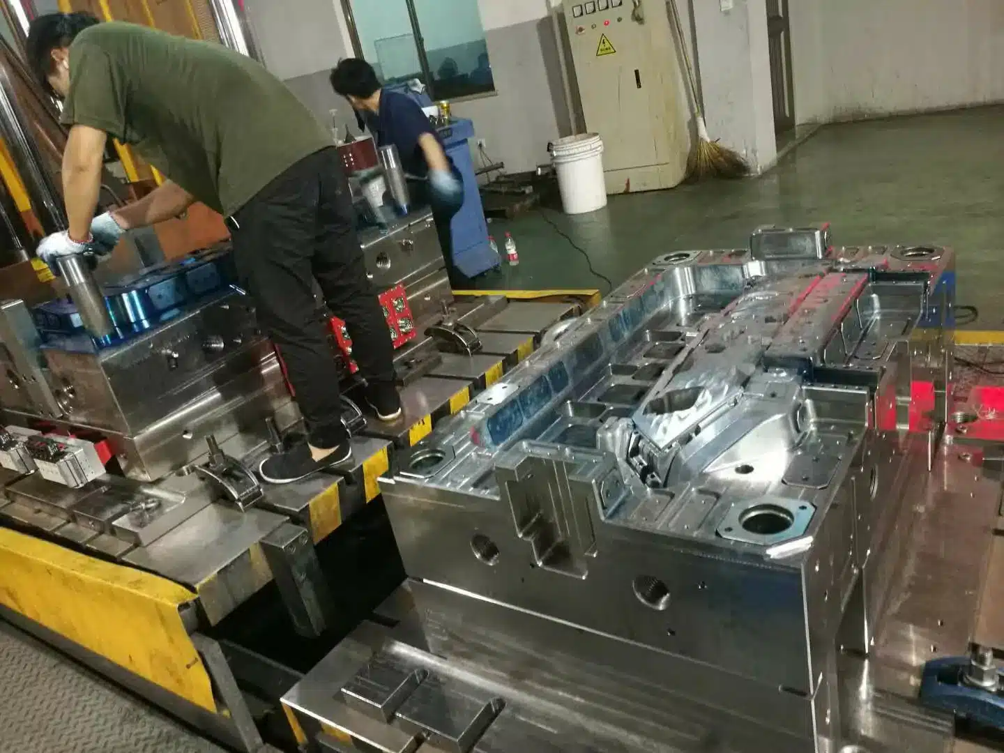
The final mold is a straightforward 2-plate layout with a 1×2 family arrangement — upper shell in one cavity, lower shell in the other, gated from a symmetric cold runner. Cavity and core are S136 stainless (pre-hardened, corrosion-resistant, ideal for PC because PC’s off-gassing during molding attacks softer tool steels over time). The mold base is a QD1608xx series standard base.
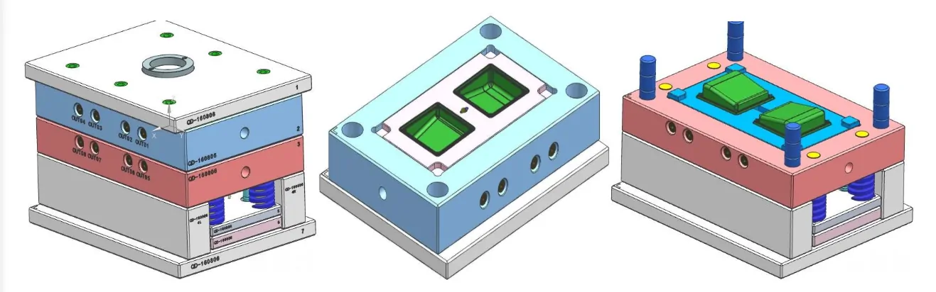
Ejection is via ejector plate driven by a hydraulic ejector from the press. Cooling is drilled straight-line channels in both cavity and core plates — no baffles or bubblers required for this cavity depth. The two cavities are cooled in parallel to keep cycle time balanced.
If you are sourcing a PC enclosure mold in China and your part looks anything like this — shallow shell, corner bosses, snap-fit or screw-attached lid, cosmetic A-surface — you can use this DFM as a checklist before you send your files out for quote. Fix the corner-R uniformity yourself. Decide on insert vs. one-piece boss construction. Split your interior and exterior finish specs. You will get better quotes and faster tooling.
If you want us to run the DFM for you, send the STEP file and a target annual volume. Turnaround is typically 3 to 5 business days.
Result — the mold ran, and here is the part on the scale
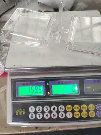
The mold went into production and produced the two shells at a combined shot weight of 159.54 grams, matching our mold-flow prediction within 1%. First-shot samples were dimensionally in tolerance on both parts, with no sink marks on the reduced corner-R zones (finding #1 was correctly resolved), no drag on the ribs (finding #3 was correctly resolved), and clean parting-line witnesses where predicted around the boss inserts (finding #5, matching customer expectation).
The DFM report added roughly two weeks to the front end of the project. It removed a documented three-to-four-week risk window on the back end for corner-R sink correction, which would have required insert re-machining and re-texturing. Net schedule impact: about ten days saved. Net tooling cost impact: about 1,500 USD in avoided rework, at a DFM engineering cost of under 500 USD.
This is what a DFM is supposed to do. It is not a formality and it is not a sales tool. It is the cheapest engineering hour you will spend on the whole program.
Frequently asked questions
How long does a DFM report take for a mold like this one?
For a 1×2 family mold at this complexity — shell parts, no slides, standard gating — we deliver the DFM in 3 to 5 business days from receipt of usable STEP files. Complex parts with slides, lifters, or unfamiliar resins can push it to 7 to 10 days.
Do we charge for DFM?
DFM is included at no separate charge when it is done as part of a quoted mold project with Topworks. If you want DFM only, without committing to tool the mold with us, we can quote a standalone DFM engagement — typically 300 to 800 USD depending on part complexity.
Why does PC need such careful wall thickness inspection?
Polycarbonate has moderate shrinkage (0.5% to 0.7%) but a wide processing window and slow crystallization behavior. The combination means that non-uniform wall thickness produces very visible defects — sink marks on thick sections, warpage on thin sections. PC also has enough transparency in natural grades that internal voids show through as haze. Wall thickness discipline is the single highest-yield DFM check for PC.
Why S136 steel instead of P20 or H13 for a PC mold?
PC off-gasses small amounts of corrosive species during molding, particularly with flame-retardant grades like ML945. P20 will corrode on the parting line and around gates within 50,000 to 100,000 shots. S136 is a stainless tool steel that resists this corrosion and holds SPI-A finish for the life of the tool. For any PC production mold intended for 500,000+ shots we specify S136 by default — see our mold steel comparison for the full breakdown.
What is the difference between a sub gate and an edge gate on this part?
An edge gate on this part would leave a visible gate vestige on the parting-line edge of the enclosure that would require secondary trimming. A sub gate enters the cavity from below the parting line, so it self-shears at ejection and leaves only a small witness on the interior wall. On a 1×2 family mold running hundreds of thousands of sets per year, the labor saved on gate trimming justifies the sub gate every time.
Can the corner R be reduced further to strengthen the corner?
Reducing the corner R helps wall thickness uniformity but too small a radius creates stress concentration and molding fill issues. Our target for this part was 1.0 to 1.5 mm external corner R with a matching internal core-out, giving uniform 2.5 mm wall thickness through the corner. Below 0.5 mm external R, you start seeing corner fill problems on PC at 2.5 mm wall thickness.
Bottom line
A proper DFM caught four material findings on this PC enclosure before we cut steel — corner R uniformity, ejection layout on the ribs, insert-line disclosure on the bosses, and interior finish confirmation. Fixing them at DFM cost the customer under 500 USD in engineering time. Fixing them after the mold was cut would have cost 1,500+ USD and three weeks of schedule. That ratio — engineering time up front versus rework time on the back end — is the reason DFM exists, and the reason we do not quote a mold without one.
If you have a PC or engineering-resin enclosure project you want reviewed, send the STEP, the resin, and the target annual volume. We will come back with a DFM report and a mold quote in the same envelope.

