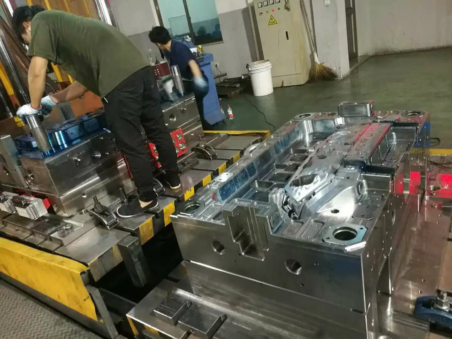

Press Room Operations
The Plastic Molding Process Cycle
Mastering the plastic molding process cycle in the press room requires coordinating material charging, low-to-high pressure mold closing, volatile gassing, thermal curing or cooling, and automated part ejection. Total cycle duration directly determines machine hourly output and piece-part unit cost.
- 3 Core Cycle Phases: Material charging/loading, pressurized heat hold (curing/cooling), and mechanical or pneumatic part ejection.
- Clamping & Gassing Pressure: Close softly on low pressure, apply high clamping pressure (around 3,000 psi), momentarily crack open to vent trapped gas/moisture on thick sections, then lock for cure.
- Hold / Cure Time Range: Ranges from 45 seconds up to 10 minutes depending on wall thickness and draw depth.
- Thermal Contraction at Open: Molding temperatures averaging 350°F drop at mold opening, inducing roughly 0.006 in. per linear inch of thermal shrinkage that aids cavity release.
1. Material Charging: Preforms vs. Volumetric Powder Loading

| Cycle Stage | Key Operational Parameter | Shop-Floor Control Method |
|---|---|---|
| 1. Material Charging | Compressed pellet preforms vs. weighed/volumetric powder | Multi-cavity sliding loading racks pre-filled during the previous cure cycle |
| 2. Mold Closing & Gassing | Low-pressure approach → 3,000 psi high pressure → momentary gas relief | Cam-actuated automatic cycle controllers prevent premature material chilling |
| 3. Curing / Cooling Hold | 45 seconds to 10 minutes at ~350°F | Governed by wall thickness and draw depth; timed via automated press clocks |
| 4. Part Ejection | Knockout pins, comb boards, or compressed air (0.006 in./in. shrink) | Undercut retention grooves on top/bottom forces + brass air-nozzle flash clearing |

The method of charging mold cavities depends on part geometry, die capacity, and whether the press runs automated thermoplastic screw feeding or compression/transfer preforms. In compression and transfer molding, loading compressed pellet preforms is more economical than loose powder. Toolrooms build dedicated multi-cavity loading racks with receptacles matching the exact cavity footprint.
While the press cures the current shot, the operator pre-loads the sliding rack for the next cycle. Once the finished shot ejects, the operator positions the loader over the lower die half and slides the bottom retainer plate to drop all preforms into the cavities simultaneously.
Injection Molding Calculator
Engineering Tool — Cooling · Ejection · Shrinkage · Clamping · Cycle
Cooling System Design
Calculate theoretical cooling time, channel layout, and efficiency. Cooling typically accounts for 50–70% of total cycle time.
Channel pitch: P ≤ 3d Channel-to-cavity: L = 1.0 – 1.5 × d
Ejection Force Calculation
Determine total ejection force and verify ejector pin stress against the allowable limit.
Pin Stress: σ = Fper pin / Apin ≤ [σ]
Shrinkage Compensation
Calculate cavity dimensions accounting for material shrinkage and machining tolerance direction.
Shrinkage: ΔD = Dpart × S
| Material | Range | Typical | Note |
|---|---|---|---|
| PP | 1.0–2.5% | 1.5% | High |
| ABS | 0.4–0.8% | 0.6% | Stable |
| PA66 | 1.0–2.5% | 2.0% | Moisture-dependent |
| PC | 0.5–0.7% | 0.6% | Stable |
| HDPE | 1.5–3.0% | 2.0% | Anisotropic |
| POM | 1.9–2.5% | 2.2% | Uniform, high |
| PS | 0.2–0.8% | 0.5% | Low |
| PMMA | 0.2–0.5% | 0.3% | Very low |
Clamping Force & Shot Size
Calculate minimum clamping force for machine selection, and theoretical shot volume and weight.
Shot Volume: Q = π/4 × D² × S (cm³) Weight: G = Q × η × ρ
Cycle Time & Production Output
Sum all process stages to calculate cycle time, hourly rate, daily and annual production capacity.
When powder is used—common on deep-draw parts where depth is the largest dimension—the charge is weighed on a balance scale or metered volumetrically to maintain shot-to-shot consistency.
2. Three-Stage Mold Closing and Volatile Gassing

Closing a loaded mold involves three distinct hydraulic operations. First, low-pressure oil advances the ram upward gently until the mold halves touch. Second, high pressure (approximately 3,000 pounds per square inch) is applied and momentarily released to vent trapped air, moisture, and volatile gases before the plasticized charge chills. Third, full clamping pressure locks the die closed for the curing or packing phase.
This momentary pressure relief after initial closure—known as gassing (or breathing)—is critical on thick-walled parts to prevent internal blisters and porosity, though thin-walled geometries often run without a gassing pause.
3. Cure Time and Automatic Cycle Control

Hold or cure time—the duration the material remains under combined heat and pressure—ranges from 45 seconds up to 10 minutes depending on wall thickness and draw depth. Thick sections and deep vertical walls require longer residence under pressure so the melt flows completely up the cavity sides and solidifies without distortion.
On self-contained automatic presses, programmable cycle controllers regulate low-to-high pressure switchover, cam-timed gassing, and cure duration automatically. The operator simply loads the charge and presses the cycle start button, allowing one technician to tend one, two, or three presses simultaneously depending on cycle length.
4. Part Ejection, Thermal Shrinkage, and Air Blow-Off

When the mold opens, molded parts cling to either the upper force plug or lower cavity depending on draft and deliberate retention undercuts. Mechanical ejector pins (knockout pins) are the primary release method: as the ram descends, pin bars push the entire shot clear so a catch tray or comb-shaped stripper board can collect all parts at once.
Between every cycle, the operator uses a brass-nozzle compressed air line to blow residual flash off the parting line Faces before loading the next shot. Because molding temperatures average around 350°F, exposure to ambient air upon mold opening causes linear thermal shrinkage of roughly 0.006 in. per linear inch. When part geometry prohibits knockout pins, directing a blast of cold compressed air against the hot part accelerates this 0.006 in./in. contraction so the piece releases cleanly from the cavity. Adding molded-in metal inserts before mold closure follows the same sequence, extending overall cycle time proportionally—a key variable when computing piece-part molding costs.
Looking to optimize cycle time or build high-cavitation production tooling? Share your part specifications with our engineering team.
Get a Tooling & Cycle Time Estimate
