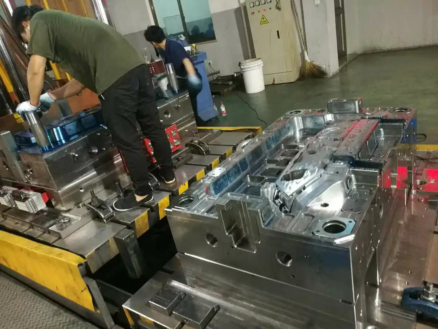

Composite & Fiber-Reinforced Tooling
Reinforced Plastics Molding: Processes, Pressures, and 16 Design Rules
The term “reinforced plastics moldings” refers to composite structural parts manufactured by impregnating fibrous reinforcement cloth or mat with liquid thermosetting or thermoplastic resin, laminating multiple plies, and curing under heat and pressure into a dense solid (distinct from stock flat high-pressure laminate sheets).
- Matrix Resins & Fibers: Polyesters, phenolics, epoxies, melamines, and silicones reinforced primarily with glass cloth/mat (plus cotton, nylon, or specialty fibers).
- Pressure Progression by Process: Contact hand lay-up (0 psi ambient cure), Vacuum Bagging (~12 psi), Pressure Bagging (up to 50 psi), Autoclave Molding (50 to 100 psi hot air/steam), and Matched Metal Die Molding (parts up to 60 sq ft cured at ~240°F).
- Cardinal DFM Rule: Consult your custom mold maker at the initial concept stage and mold directly to net dimensions—cured composite parts cannot be “sprung” or bent into alignment after molding.

Matrix Materials and 6 Molding Methods

Materials: Commercial reinforced plastics primarily combine thermosetting resins—polyesters, phenolics, epoxies, melamines, and silicones—with glass fiber cloth or chopped strand mat (alongside specialized cotton or synthetic nylon fiber mats used to reinforce vinyls and acrylics).
| Molding Method | Applied Clamping Pressure / Temp | Glass Content & Part Size | Tooling & Production Economics |
|---|---|---|---|
| Contact Molding | 0 psi (ambient room cure, no external heat) | Low-to-moderate glass ratio; open lay-up | Uses a low cost mold; manual spray/brush lay-up for prototypes |
| Vacuum Bag Molding | ~12 psi atmospheric vacuum under PVA film | Higher glass content than contact lay-up | Low tooling cost; improved void removal |
| Pressure Bag / Autoclave | Up to 50 psi (bag) or 50–100 psi (steam autoclave) | High glass-to-resin structural ratio | Tailored pressure bag + autoclave vessel for aerospace/marine |
| Flexible Plunger Molding | High uniform fluid pressure via heated female cavity + rubber plug | High glass content; restricted to small/medium parts | Metal female cavity + medium-hard shaped rubber plunger |
| Vacuum Injection Molding | Vacuum suction draws resin up from bottom moat between 2 FRP molds | Low glass content; excels on large air-free parts | Two matched glass-reinforced plastic molds |
| Matched Die Molding | Telescoping metal dies heated to ~240°F (steam/electric) | Parts up to 60 sq ft; precise wall control | Delivers the lowest cost moldings and highest output on long runs |
Contact molding: Layers of reinforcing mat or woven cloth are positioned by hand against a low cost mold and saturated with liquid resin via spraying or brushing. The laminate cures at room temperature without external heat or clamping pressure.
Vacuum bag molding: Follows hand lay-up, but covers the wet laminate with flexible polyvinyl alcohol (PVA) sheeting and draws a vacuum between the bag and mold face—applying roughly 12 psi of consolidation pressure to boost glass content.
Pressure bag molding: Places a tailored inflatable bag over the sheeting at up to 50 psi internal pressure (or loads the assembly into a hot-air/steam autoclave at 50 to 100 psi) to achieve high structural glass loadings.
Flexible plunger molding: Loads glass and resin into a heated metal female cavity and compresses the charge with a shaped, medium-hard rubber plug that transmits uniform fluid-like pressure across small-to-medium parts.

Vacuum injection molding: Clamps dry reinforcement between two matched molds (often made of FRP), pours resin into a perimeter bottom moat, and uses vacuum suction to draw resin upward through the fibers—producing large, void-free parts.
Matched die molding: Uses close-fitting telescoping metal male and female dies heated to roughly 240°F to seal resin and shear-trim the reinforcement automatically on parts up to 60 sq ft. For high-volume runs, matched metal dies deliver the lowest cost moldings and fastest cycle rates.
16 Engineering Design Rules for Molded Reinforced Plastics

Designing molded reinforced plastics parts requires controlling five interacting process variables:
- Resin formulation, including mineral fillers, catalysts, and hardeners,
- Reinforcing fiber geometry (woven cloth, directional roving, or random mat),
- Resin-to-reinforcement weight ratio,
- Degree of fiber wet-out and resin saturation, and
- Curing temperature profile and cycle duration.
The cardinal rule of composite tooling is: consult your custom mold maker during the initial CAD stage, and apply these 16 DFM guidelines:
- Integrate parts to eliminate secondary fasteners and sub-assemblies.
- Make prototypes to validate fiber lay-up and load paths before cutting production steel.
- Mold to exact net dimensions; cured composite parts cannot be “sprung” or forced into shape during assembly.
- Use stress formulas specifically validated for anisotropic fiber-reinforced plastics.
- Define all thermal, chemical, and mechanical service conditions upfront.
- Match part geometry to the chosen molding pressure method.
- Use sandwich core construction where maximum strength-to-weight stiffness is required.
- Increase local rigidity in high-stress zones by: a) raising glass loading, b) aligning unidirectional fibers along the load vector, c) adding edge flanges and lips, d) molding in ribs, corrugations, beads, and dimples, e) thickening the wall, f) replacing flat panels with domed/curved sections, and g) using sandwich cores.
- Avoid drastic wall-thickness transitions that trap resin pools and cause cracking.
- Avoid sharp internal corners; specify generous radii so glass fibers conform without bridging.
- Specify maximum allowable draft angles on vertical walls.
- Eliminate undercuts to allow straight-pull matched die operation.
- Use molded-in holes only where fiber displacement does not weaken weld zones.
- Compensate for mold shrinkage in the steel cavity dimensions.
- Specify practical commercial dimensional tolerances.
- Balance laminate symmetry to prevent post-mold warpage.
Designing a glass-filled thermoplastic or matched-die composite component? Send your 3D CAD to our tooling engineers for a free DFM review.

