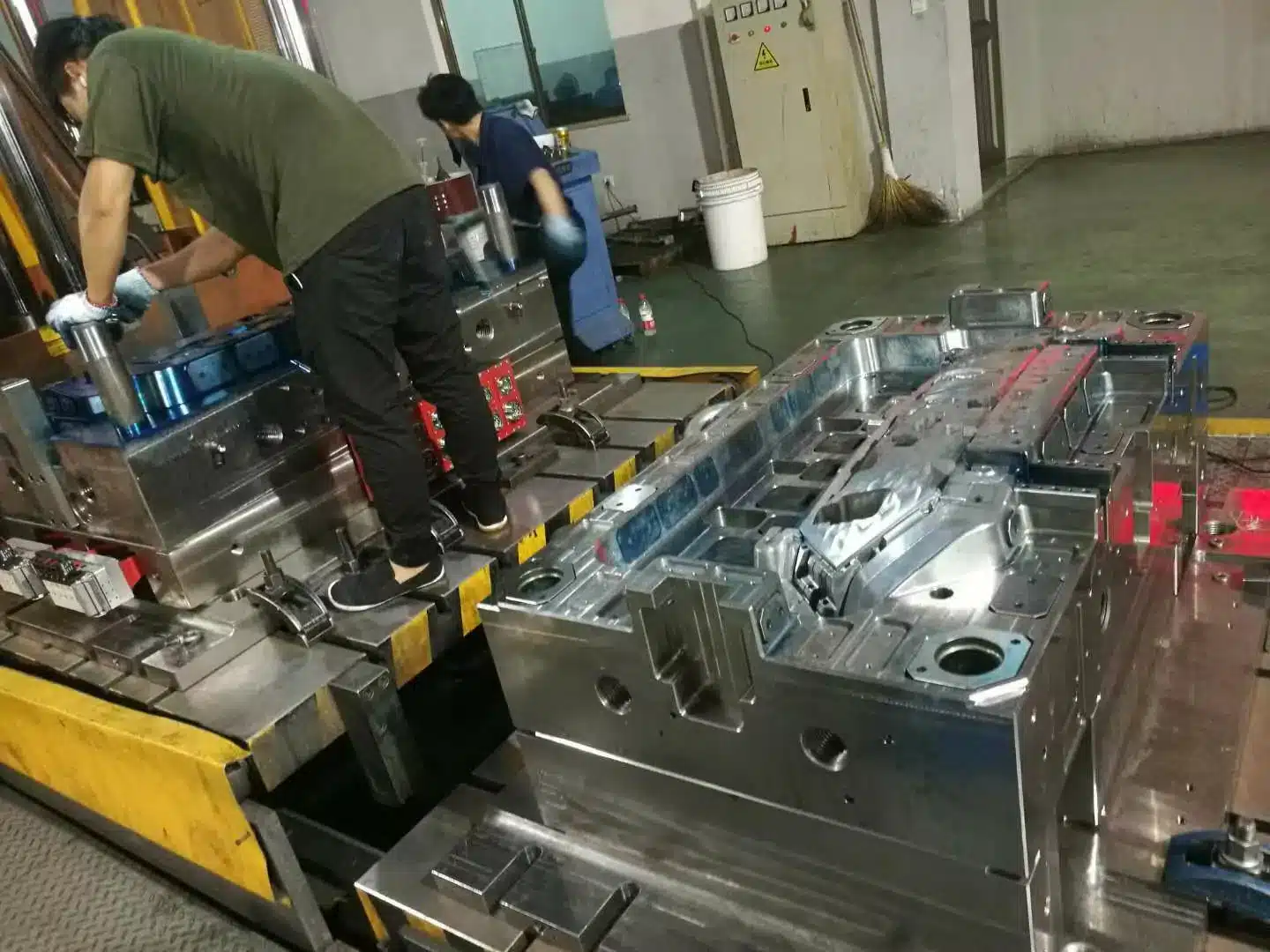

Most “mold design” articles are really part design articles. Wall thickness, ribs, draft. That’s useful, and we cover it on our plastic part design page.
This one is about the tool itself. The steel. Where the plastic goes in, how the heat comes out, and how the part gets pushed off the core without a mark.
I’ve reviewed mold designs in Huangyan for over twenty years. What follows is the order we actually work in, with the numbers our designers use on real jobs.
- Mold type (2-plate, 3-plate or hot runner)
- Parting line, cavity and core
- Number of cavities and their layout
- Feed system: sprue, runners and gates
- Venting and cooling
- Ejection and side actions for undercuts
- Steel grade and mold base
1. What the mold designer needs before drawing anything
A designer who starts without full information will redraw the tool later. Usually after steel is cut.
Before we open the CAD software, we want these on the table:
| Input | Why it changes the mold |
|---|---|
| 3D file (STEP/IGES) + 2D drawing | The 3D defines geometry. The 2D tells us which dimensions are critical and what tolerance they carry. |
| Exact resin grade | “PA66” is not enough. PA66 GF30 shrinks differently in flow and cross-flow. It also wears gates faster. |
| Annual volume and tool life | Decides cavity count, steel grade and whether a hot runner pays off. |
| Cosmetic faces | Gate marks, ejector marks and parting lines must stay off these. |
| Surface finish / texture | Texture depth sets the minimum draft. See our surface finish guide. |
| Target molding machine | Tie-bar spacing, clamp tonnage and shot size limit how big the tool can be. |
| Assembly and function | A snap fit or sealing face may need tighter steel, a different gate side, or no ejector there at all. |
If the part itself needs changes, this is the moment. A DFM review costs a day. A steel change after T1 costs a week and real money. Our polycarbonate enclosure case study shows what that review looks like in practice.
2. Choose the mold type: 2-plate, 3-plate or hot runner
This choice comes early because it decides where gates can go. Everything after depends on it.
| Type | How it works | Good for | Trade-off |
|---|---|---|---|
| 2-plate cold runner | One parting line. Runner and parts eject together. | Most parts. Edge or submarine gating. | Runner scrap. Gate must sit near the part edge. |
| 3-plate cold runner | A second opening strips the runner from pin-point gates. | Center gating without a hot runner. Multi-cavity small parts. | Longer opening stroke. More runner waste. |
| Hot runner | Heated manifold keeps plastic molten up to the gate. | High volume, large parts, cosmetic parts, expensive resin. | Adds roughly USD 2,000–10,000+ to the tool. Needs a controller. |
Our rule of thumb: if the runner weighs more than about 30% of the shot and volume is above a few hundred thousand a year, price a hot runner. The resin savings often cover it in the first year. The full cost picture is in our mold cost guide.
3. Parting line, cavity and core
The cavity forms the outside of the part. The core forms the inside. Where they meet is the parting line.
Most of the time the cavity sits on the fixed half and the core on the moving half. Plastic shrinks onto the core. That’s what holds the part on the ejection side when the mold opens.
Main components of a plastic injection mold
- Core and Cavity — form the shape of the plastic part.
- Runner System — guides molten plastic into the cavity.
- Gate — entry point where plastic flows into the part.
- Cooling Channels — cool the plastic quickly and evenly.
- Ejector Pins — push the finished part out of the mold.
- Slider or Lifter — release side holes and undercuts.
Where to put the parting line
- At the largest outline of the part, seen from the opening direction.
- Away from cosmetic faces. A parting line always leaves a faint witness line.
- On a flat or simple surface if possible. Stepped lines cost more to fit.
- Where shutoffs are needed, keep shutoff faces at 5–7° or more. Flatter shutoffs wear and flash.
Get the parting line right and many undercuts disappear. We’ve removed a slider more than once just by moving the line 2 mm.
Shrinkage goes into the steel
Cavity and core are cut oversize by the resin’s shrinkage. Pick the wrong value and every part comes out of tolerance.
| Resin | Typical shrinkage (%) | Note |
|---|---|---|
| ABS | 0.4–0.7 | Stable and forgiving |
| PC | 0.5–0.7 | Low but stress-sensitive |
| PMMA | 0.2–0.8 | Depends on wall and packing |
| PP | 1.2–2.0 | Varies with wall thickness |
| HDPE | 1.5–3.0 | High and hard to predict |
| POM | 1.8–2.5 | Crystalline, high shrink |
| PA66 (unfilled) | 1.0–2.0 | Absorbs moisture after molding |
| PA66 GF30 | 0.3–0.8 flow / 0.8–1.2 cross | Anisotropic. Warp risk. |
These are starting values. For tight parts we use the resin supplier’s data for that exact grade, then leave steel-safe on critical dimensions. More on this in controlling injection molding dimensions.
“Steel-safe” means cutting so the fix is removing steel, never adding it. Adding steel means welding. Welding on a cavity is a last resort.
4. Cavity count and layout
Start from demand, then check the machine.
A simple way to estimate:
Cavities = (annual parts × cycle time in s) ÷ (production hours × 3600 × efficiency)
Example. One million parts a year. 30-second cycle. 6,000 machine hours at 85% efficiency.
1,000,000 × 30 ÷ (6,000 × 3,600 × 0.85) = 1.6. So two cavities.
Then check three limits:
- Clamp force. Projected area of all parts plus runner, times cavity pressure. For mid-viscosity resins we use about 0.3–0.5 t/cm². Add 10–20% margin.
- Shot size. The full shot should use roughly 20–80% of the barrel capacity.
- Tolerance. Every extra cavity adds variation. For tight parts, fewer cavities is often cheaper overall.
Layout matters as much as count. In a cold runner tool, every cavity should see the same flow length. An H-pattern layout does this. A row of cavities off one runner does not. The cavity nearest the sprue fills first and packs hardest.
Never mix different parts in one family mold if one of them has tight tolerances. You’ll end up tuning the process for one part and scrapping the other.
5. Sprue, runners and gates
The sprue takes melt from the nozzle. Runners carry it across the mold. The gate is the small opening into the cavity.
Runners
- Full-round runners flow best. They need machining on both mold halves.
- Trapezoidal runners sit on one half only. Cheaper, slightly less efficient.
- A common starting size: runner diameter ≥ part wall thickness + 1.5 mm.
- Add a cold slug well at the end of each runner branch. It catches the cold front of the melt.
Gates
The gate decides how the part fills, where weld lines form, and what mark is left behind. It is the single most argued-about detail in our design reviews.
| Gate type | Auto degate? | Mark left | Typical use |
|---|---|---|---|
| Edge (side) gate | No | Visible at edge, trimmed | General parts, 2-plate tools |
| Submarine (tunnel) | Yes | Small, on a side wall | Small to mid parts, high volume |
| Banana / cashew | Yes | Hidden underside | When the gate must sit under the part |
| Pin-point | Yes | Tiny dot, 0.5–1.5 mm | 3-plate tools, center gating |
| Fan / film | No | Long trimmed edge | Flat parts, clear parts, low warp |
| Direct sprue | No | Large, must be cut | Single-cavity deep parts like buckets |
| Hot tip / valve gate | Yes | Small ring or near none | Hot runner, cosmetic, high volume |
Three gate rules we rarely break:
- Gate into the thickest section. Plastic should flow thick to thin, so the thick area can still be packed.
- Gate thickness at about 50–80% of the wall it enters. Too thin freezes early and causes sink.
- Know where the weld lines will land before steel is cut. Move them off loaded areas and cosmetic faces.
We go deeper on each type in our gate design article. You can also try gate positions on the simulator below.
Gate and runner improvement case: A thick wall polycabonate cover,bubblbes were always found inside the thick wall,we made the runner,sprue and gate thicker,the problem was solved

6. Venting: the cheapest feature, often forgotten
When plastic fills the cavity, the air inside has to leave. If it can’t, it compresses and heats up. You get burn marks, short shots and weak weld lines.
Vents are shallow grooves ground on the parting face. Deep enough for air. Too shallow for plastic.
| Resin group | Vent depth (mm) |
|---|---|
| PA, PP, PE, POM (low viscosity) | 0.01–0.02 |
| ABS, PS, PC/ABS | 0.02–0.03 |
| PC, PMMA (higher viscosity) | 0.03–0.05 |
Keep the vent land about 0.8–1.5 mm long. After that, open it to a deeper relief channel, around 0.3–0.5 mm, out to the mold edge.
Put vents at the end of fill and at every weld line. Ejector pins and inserts also vent, but don’t count on them alone.
7. Cooling: where the cycle time is won or lost
Cooling usually takes 60–70% of the whole cycle. Shave cooling time and you shave cost on every single part.
Poor cooling also causes warp. One side of the part runs hotter, shrinks more, and pulls the part out of shape.
Numbers our designers start from
- Channel diameter: 6 mm for small tools, 8–12 mm for mid-size, larger for big automotive tools.
- Channel center to molding surface: about 1.5–2× the channel diameter.
- Spacing between channels: about 3–5× the diameter.
- Inlet to outlet temperature difference: under 3 °C on precision tools.
- Flow should be turbulent. Laminar water carries far less heat.
Deep cores are the hard part
A straight drilled line can’t reach inside a deep core. We use baffles or bubblers to push water up into it. For thin cores where nothing fits, we use beryllium copper or other high-conductivity inserts.
Cooling should be designed before ejectors, not after. Once ejector pins are placed, the water lines have to snake around them. We’ve seen tools where cooling was drawn last, and the core ran 20 °C hotter than the cavity. The parts warped every time.
- Map hot spotsThick walls, deep cores, gate area
- Lay out channelsFollow the part shape, keep even distance
- Add baffles/bubblersReach deep cores
- Place ejectorsAround the water, not over it
- Check by simulationSurface temperature within a few degrees
8. Ejection: getting the part off the core
The part shrinks onto the core and grips it. Ejection has to push it off evenly. Push one corner harder and the part bends, cracks or leaves a white stress mark.
| Method | Best for | Watch out for |
|---|---|---|
| Round ejector pins | Most parts. Place under ribs, bosses, corners. | Witness marks. Keep off cosmetic faces. |
| Sleeve ejectors | Bosses and tall round features | Need a fixed core pin inside |
| Blade ejectors | Thin deep ribs | Fragile, wear fast. Last choice. |
| Stripper plate / ring | Thin-wall round parts, cups, caps | Higher tool cost |
| Air poppets | Deep containers that vacuum-lock | Usually combined with a stripper |
Use the largest pins that fit. Small pins punch into the part. Set the ejector stroke to part depth plus about 5–10 mm.
Draft is what makes ejection possible. Start at 1° per side. Add roughly 1° for every 0.025 mm of texture depth. Polished cores in PC can go lower. Textured ABS cannot.
Deep buckets are a good example of everything at once. Our paint bucket mould guide shows how stripper ring and air ejection work together.
9. Undercuts: sliders and lifters
An undercut is any feature that blocks the part from coming straight off. Side holes, external clips, internal snap hooks.
First question: can the part be changed to remove it? A pass-through shutoff or a moved parting line often does the job. If not, the mold needs a side action.
- Slider: for external undercuts. An angled pin drives the slider sideways as the mold opens. Angle pins usually run 15–25°. The locking wedge is 2–3° steeper so it holds the slider under injection pressure.
- Lifter: for internal undercuts. It rides on the ejector plate and moves up and inward. Lifter angles typically sit around 5–12°. Steeper angles wear and stick.
- Collapsible core or unscrewing: for internal threads and full internal rings.
Every action adds cost, cycle time and a part that can wear. Each one also needs its own cooling if it forms much of the part.
[tw_slider_lifter]One trap: if a slider moves back over ejector pins, the pins must retract first. That needs an early-return system. Miss it and the slider crashes into the pins on the first close.
10. Steel and mold base
Steel choice follows tool life, resin and finish. Not the other way around.
| Steel | Hardness (HRC) | Typical life | Used for |
|---|---|---|---|
| P20 | 28–34 (pre-hardened) | Up to ~300k shots | General parts, large tools |
| 718H | 33–38 (pre-hardened) | ~300k–500k | Better polish than P20, mid volume |
| NAK80 | 37–43 (pre-hardened) | ~500k | Mirror polish, clear and glossy parts |
| H13 | 48–52 (hardened) | 1M+ | Glass-filled resins, high volume |
| S136 | 48–52 (hardened) | 1M+ | PVC, medical, optical, corrosion resistance |
US buyers often specify tools by SPI class. Class 101 is built for over a million cycles. Class 103 is for under 500k. Class 104 is under 100k, usually softer steel. Ask your supplier which class they’re quoting. Two “identical” quotes can be two different classes.
The mold base holds everything: plates, guide pins, ejector system. We mostly use LKM standard bases. HASCO or DME parts are available when a US or EU customer’s maintenance team needs them.
11. Mold flow analysis and design review
Before steel is ordered, we simulate. A mold flow run shows fill pattern, weld lines, air traps, pressure, cooling and warp.
It doesn’t replace experience. It does catch the obvious mistakes cheaply.
Here is the sequence on a typical project with us:
- DFM report1–3 days. Draft, walls, gate, undercut issues.
- Mold flowFill, pack, cool, warp check.
- 2D layoutCavity layout, mold size, gate, cooling.
- 3D mold designFull tool with every component.
- Customer sign-offSteel ordered only after approval.
- T1 trialUsually 4–6 weeks after design approval.
Insist on seeing the 2D layout and mold flow before steel is cut. If a supplier won’t share them, you’re buying a tool you’ve never seen. More on how a mold comes together in what is a plastic mold and the full injection molding process.
12. Mistakes we still see every year
- Gate on a cosmetic face. Nobody marked the faces. Found at T1. Fixed by a new gate insert and a week’s delay.
- Cooling drawn last. Ejector pins took the space. Core ran hot. Parts warped.
- Datasheet shrinkage on a glass-filled part. Flow and cross-flow shrink differently. One value can’t cover both.
- Too many cavities for the tolerance. Eight cavities quoted cheap. Half of them out of spec.
- No vent at end of fill. Burn marks in the same corner on every shot.
- Slider over ejector pins, no early return. Damaged tool on the first close.
- Zero draft “because the drawing says so.” Parts scuff or stick. Ask for draft early, not after T1.
None of these are hard to avoid. They all come from deciding too late.
Want to check your own part first? Our interactive design tools cover wall thickness, ribs, draft and gates.
Send us your part file. We’ll show you the mold.
Upload a STEP or IGES file. You’ll get a DFM report with gate position, parting line, cavity layout and a tool quote, usually within 24 hours. NDA on request.
Get a free DFM review →FAQ
What are the main parts of an injection mold?
Cavity and core form the part. The feed system brings plastic in. Cooling lines remove heat. The ejector system pushes the part out. The mold base holds it all together.
How long does injection mold design take?
DFM takes one to three days. Full 3D mold design takes about three to seven days. First samples usually arrive four to six weeks after design approval.
What is the difference between cavity and core?
The cavity forms the outside of the part, usually on the fixed half. The core forms the inside, on the moving half. The part shrinks onto the core and ejects from that side.
Where should the gate be placed?
Gate into the thickest section, away from cosmetic faces. Check where weld lines will form. Keep them off loaded or visible areas.
When is a hot runner worth it?
Consider it for high volume, large parts, expensive resin, or when the cold runner is heavy. It adds tool cost but saves resin and cycle time.
Which steel is best for an injection mold?
P20 or 718H suits most mid-volume tools. H13 handles glass-filled resin and high volume. S136 suits PVC, medical and optical parts. NAK80 suits mirror finishes.
The short version: a good mold is decided early. Parting line, gate and cooling come before anything else. Ask to see the layout and mold flow before steel is cut. Most expensive mold problems start as one quick decision nobody questioned.

