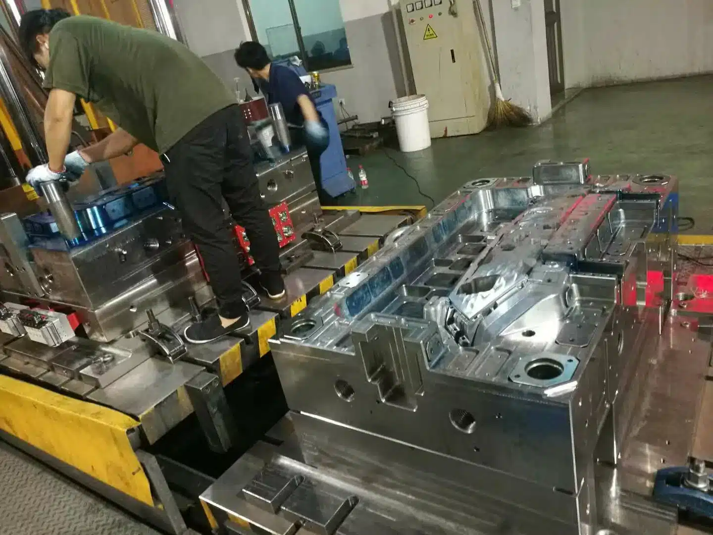

PC Mold Design
PC Runner and Gate Design That Stops Splay, Cold Slugs and Cracking
Most polycarbonate defects are designed into the tool, not created at the press. PC runner and gate design decides whether a clear part shows splay, cold slugs or flow marks. It also decides whether that part cracks three months into service. PC fills hot and fast. A runner layout that works fine for ABS or PP will not hold up.
Four decisions carry most of the risk on a PC tool. Run the runner S-shaped or L-shaped, never straight into the gate. Make the cold slug well about twice the runner diameter, with a volume at least 1–2 times the cross-sectional volume of the runner feeding it. Gate thickness sits at 50–80% of the wall, and PC belongs at the top of that band. Use a valve gate — 4 mm and up, typically 6–8 mm on thick-wall clear parts — not a hot tip.
What PC Does That Changes the Mold
Buyers often send us a PC part drawn the way an ABS part is drawn. Thin walls, long flow, sharp ribs. The quote comes back with a wall thickness change nobody wanted and a mold temperature nobody expected. Every rule below traces to the four properties in this table.
| Property | What it means for the mold |
|---|---|
| Highly transparent engineering plastic (polycarbonate) | Every flaw is visible. Weld lines, splay, bubbles and flow marks all show through the part. Cavity steel is usually S136 at 48–52 HRC so it will polish and stay corrosion free. |
| Relatively poor flow | Thin walls fight you. PC parts run a 1.0–3.0 mm wall, and transparent parts sit near 2.0 mm. Keep flow length to wall thickness at or below 150, so roughly 300 mm of flow at a 2 mm wall and 450 mm at 3 mm. Hold wall variation inside ±25% of nominal and keep inside radii at R ≥ 0.25–0.5 × wall. |
| High processing temperature | Melt runs 280–320°C, mold 80–110°C, with clear parts usually at the upper half of that band. Steel and cooling have to live at that temperature. |
| Moisture sensitive and shear sensitive | Dry at 90–110°C for at least two hours, then run a PC screw with back pressure in the 6–15 MPa band. A general-purpose screw shears the melt and you pay at the gate. |
PC is an engineering thermoplastic that has to be injected hot, fast and clean. The mold’s only job is to let that happen. No trapped cold material, no trapped air, no locked-in stress.
Use an S-Shaped or L-Shaped Runner
A straight shot from sprue to gate is the fastest way to put a cold slug on a clear surface. The runner should turn before it reaches the gate.
That turn does two jobs. The melt front slows and changes direction, so it stops jetting into the cavity. The cooled leading edge then carries past the gate branch and parks in the dead end instead of entering the part. On a transparent component you see the difference on the first T1 shots, as a streak near the gate or no streak at all.
Size the cold runner before you shape it. The sprue runs 4–8 mm on small and medium parts and 6–10 mm on large ones, and branch runners sit just under that, commonly 4–7 mm, in a full round or trapezoidal section. The rule that catches people out is simple: no length of runner may freeze before the gate does.

Cold slug wells: long enough to do the job
The cold slug well is the runner extension past the turn. For PC, make it about two times the runner diameter, and check the volume as well: the well should hold at least 1–2 times the cross-sectional volume of the runner feeding it. Put one at the base of the sprue, at every runner corner, and ahead of each gate. A short well fills up early and starts feeding the cold front back toward the cavity. With a proper well on an L-runner, the gate area comes out clean and stays clean through the run.
Extend the cross runner to kill flow marks
Flow marks get blamed on melt temperature more often than they deserve. Sometimes the runner is simply too long and the very front of the melt has cooled too far. PC shows this worse than most resins. Transparent PVC is next in line.
That explains the situation where you raise melt temperature three times and nothing changes. The fix is mechanical, not thermal. Extend both ends of the cross runner by a few centimeters, and the cooled front runs into the extension instead of the part. Other resins benefit too, but on PC and clear PVC the improvement is obvious. Our gate and flow simulators show the same effect if you want to see it move.
Size the Cold Sprue Bigger Than You Think
Small sprues freeze. Then you get short shots, an unstable cycle and an operator chasing pressure for the rest of the shift.
A workable reference is a small-end diameter of 4–8 mm, and on PC you take the top of that band, 6–8 mm, opening to about 10 mm at the parting line on large parts. Anyone used to PP or PE sprues will call that generous. PC needs the volume and the lower pressure drop to keep moving at high injection speed. I size these on the large side every time, because a frozen sprue costs far more than the extra material in the runner.

Gate Design for PC
Gate thickness: 50–80% of wall, and PC sits at the top
The general starting point is 50–80% of the local wall thickness, with 0.5–0.75 × wall quoted in most references. PC flows poorly and shears easily, so it belongs at the upper end of that band, around 0.7–0.8 × wall. Go thinner and you get shear heat, splay and molded-in stress. Go thicker and degating gets ugly, often leaving a vestige on a cosmetic face. That trade-off is the entire gate decision, and it is worth settling before the steel is cut.
Two numbers go with it. Gate cross-sectional area normally lands at 3–9% of the runner cross-section, and gate land stays short: 0.5–1.0 mm on thin-wall fast-filling parts, 1.0–1.5 mm on thicker slower ones. If the grade is glass filled, open the gate cross-section by roughly 10% to drop shear.
Make the first gate large
Stress concentrates at the gate. A small gate forces melt through at very high shear and leaves that stress exactly where the part will crack later. For anything that carries load or takes impact, go larger. On a cold runner pin gate, PC and other high-viscosity resins such as PMMA and POM want 1.2–2.0 mm rather than the 0.8–1.2 mm you would use on ABS or PS. If your supplier argues for a small gate purely on appearance, ask what happens to the part under load.
Gating transparent parts without weld lines
Weld lines on an optical surface are usually a reject, not a cosmetic debate. For box-shaped or simple clear parts, a single-drop hot runner with a side gate solves it. One flow front means no weld line anywhere on the visible face. Where the geometry is round — lids, rings, tubes — a diaphragm or ring gate at 0.3–0.8 mm thick spreads the front evenly and keeps shrinkage concentric. More detail on gate types sits in our mold design knowledge center.
Hot Runner Choices for PC
Hot runners suit PC well. The gate type is where tools go wrong.
- Hot tip, or pin-point, gates are a bad fit. Those tips run 0.6–2.8 mm, and PC does not flow well enough through an opening that small — it freezes or blocks.
- A single-point valve gate is the safer design. Valve gates start around 4 mm and can go larger without penalty, and on thick-wall clear parts we hold the opening at 6–8 mm in diameter to keep shear down.
A valve gate gives you clean shut-off and a large opening at the same time. Price it early, because valve gate hardware moves the tooling budget noticeably. Supplier comparisons in MoldMaking Technology are a reasonable place to start.
Troubleshooting Common PC Defects
Gate splay (air streaks near the gate)
Among GPPS, K-resin, clear ABS and PC, polycarbonate is the one that splays at the gate. It is also the hardest to clear.
The mechanism is simple enough. PC flows poorly, so it has to be injected fast, otherwise you get short shots or vibration marks. Fast injection makes the melt strike the cavity wall at the gate and rebound, trapping a thin pocket of air. Thicker parts trap more. The hot melt surface then oxidizes against that air and forms a gas film between plastic and steel. What you see is a dull matte streak that ruins transparency.
Other clear resins flow easily enough to run slower, so trimming speed and pressure fixes them. PC gives you no such room. That is why gate splay on PC counts as a real molding problem rather than a setting problem.
Check the mold side first:
- Runner goes straight into the gate instead of turning.
- No vent at the end of the flow path. Vents run 0.02–0.05 mm deep, about 1.5 mm of land, 3–12 mm wide, and belong opposite the gate, at the end of fill, at the runner tail and past the cold slug well.
- Secondary gate is too thin.
On the process side, direct injection pushes gasified bubbles into the cavity and leaves cold-slug-type marks. Slowing down trades splay for vibration marks. The S-runner, the vent and a thicker secondary gate are what actually hold.
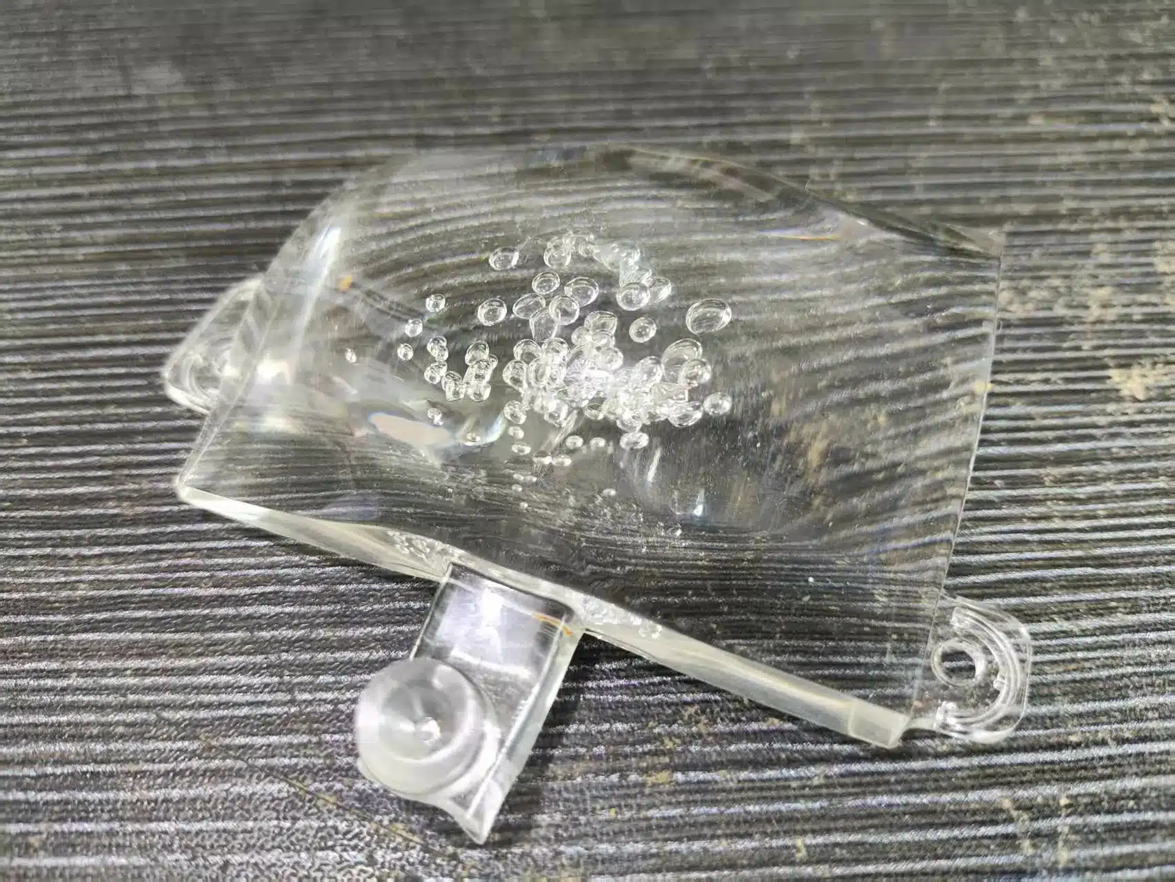
Vacuum voids in thick sections
A heavy section shrinks away from the core and leaves a vacuum void inside. On a clear part there is nowhere to hide it. Core out the thick area so the wall stays even — the same ±25% wall variation limit applies here. An insert can also take the mass out where coring is awkward. Packing harder will not cure a section that is simply too heavy for the material. We ran into exactly this on a 20L bucket mold project, where the handle boss had to be cored before anything else worked.
Cracking and brittleness
Gears and other load-bearing PC parts crack for four reasons.
- Stress at the first gate. Open the gate up.
- Weak weld lines. A weld line in a loaded area is the low-strength spot, so move the gate, move the weld, or raise melt and mold temperature there.
- Uneven loading. Spread load points across the part rather than onto one tooth or one rib.
- Grade differences. Mold temperature and drying conditions are grade-specific, and a setting that suits one grade embrittles another.
When a PC part turns brittle or hazy without warning, check melt temperature, drying temperature and drying time before you touch the mold. Those three account for most cases and save days of trial and error.
Melt temperature, drying temperature and drying time
The working window for PC is 280–320°C melt. Grades such as PC 7025A and 1250Y typically run 290–310°C inside it. The same setting makes certain other grades very brittle. For those, stay below about 290°C, sometimes lower. If the cavity still fills, run the low end and avoid degradation.
Drying follows the same split. The baseline is 90–110°C for two hours or more. 7025A and 1250Y tolerate the top of that range, and some datasheets allow a short hold at 120°C. Other grades must stay at or under about 100°C, or parts come out brittle with a whitish haze that destroys transparency.
Drying time is the one people overlook, and it causes real trouble. Two hours is a minimum, not a target, and a well-behaved grade will sit in a 50 kg hopper dryer for six or seven hours with no problem. Some grades should not sit longer than about four hours. After that comes haze and brittleness, and it worsens the longer they wait. If a hopper full lasts six hours, fill it halfway and top up more often. Random hazy shots often trace back to material baked in a hopper corner that finally drops into the barrel.
Quick reference table
| Item | Typical range from our experience | Watch out for |
|---|---|---|
| Wall thickness | 1.0–3.0 mm; about 2.0 mm on transparent parts | Hold variation inside ±25% of nominal |
| Flow length to wall ratio | L/T ≤ 150 | Long thin flow paths need a second gate, not more pressure |
| Mold temperature | 80–110°C, usually 90–110°C on clear parts | Mold steel and cooling must tolerate the heat |
| Melt temperature | 280–320°C; common grades 290–310°C | Some grades go brittle above about 290°C |
| Drying temperature | 90–110°C; about 100°C max for sensitive grades | Overheating brings haze and brittleness |
| Drying time | Two hours minimum; many grades fine for six to seven | Some grades go brittle after four hours; do not overfill the dryer |
| Back pressure | 6–15 MPa | Too low leaves unmelted material and bubbles |
| Gate thickness | 50–80% of wall; PC at 0.7–0.8 × wall | Too thin gives splay and stress |
| Gate cross-section / land | 3–9% of runner section; land 0.5–1.0 mm thin wall, 1.0–1.5 mm thick wall | Glass-filled grades need about 10% more gate section |
| Cold runner pin gate | 1.2–2.0 mm on PC | ABS-sized 0.8–1.2 mm gates burn and stress PC |
| Cold slug well | About 2× runner diameter; volume ≥ 1–2× runner section volume | Short wells let cold slugs into the part |
| Cold sprue | 4–8 mm small end (6–8 on PC), to about 10 mm on large parts | Small sprues freeze and block |
| Branch runner | 4–7 mm, slightly under the sprue | No runner section may freeze before the gate |
| Valve gate diameter | 4 mm and up; 6–8 mm on thick-wall clear parts | Do not use 0.6–2.8 mm hot tip gates on PC |
| Venting | Depth 0.02–0.05 mm, land about 1.5 mm, width 3–12 mm | Deeper vents flash; blocked vents cause burn and splay |
| Cooling channels | φ8–10 mm at a 2–4 mm wall; 15–20 mm from the cavity; 40–60 mm pitch | Keep 3–5 mm clear of ejector pins and screws |
| Coolant | 20–30 L/min per circuit; inlet to outlet ΔT 2–4°C; water 3–10°C below mold temperature | ΔT above 5°C warps the part |
| Cooling time | About 25–35 s at a 3 mm wall; 50–70% of total cycle | Cooling time scales with the square of wall thickness |
| Cavity steel | S136, 48–52 HRC | Needed for polish and corrosion resistance on clear parts |
Machine Settings That Undo a Good Mold
Skip suck-back after plasticizing
Operators pull the screw back after metering to stop the nozzle drooling. On PC that habit costs you silver streaks. Screw retraction draws air into the nozzle, and PC absorbs the moisture in that air almost instantly. The streaks appear on the part surface, and no mold change will remove them.
Clear PVC behaves the same way. It burns easily, and contact with air leaves yellow spots or black burn specks.
So avoid suck-back on PC and clear PVC. If back pressure is high and the nozzle drools, use the smallest decompression that stops it. Never let air reach the nozzle. In practice that means do not over-retract the screw. Keep back pressure in the 6–15 MPa band and leave a cushion of 5–10% of shot stroke so the screw is not bottoming out.
Run a screw designed for PC
A PC screw is not optional equipment. A general-purpose screw over-shears the melt, and that shows up as degradation, splay and brittleness. Size the machine so the shot uses 30–50% of its rated capacity — the usual engineering-resin rule — because a shot that is too small for the barrel leaves PC sitting hot and degrading. When a well-built mold throws defects nobody can explain, check the screw early. Processing coverage in Plastics Technology goes deeper on screw geometry if you want the background.
PC Runner and Gate Design Checklist
Run this list before you sign off a PC mold design.
- Runner is S-shaped or L-shaped, not a straight shot into the gate.
- Cold slug well is about twice the runner diameter and holds at least 1–2 times the runner’s cross-sectional volume.
- Cross runner extended at both ends where flow marks are a risk.
- Cold sprue is large: 4–8 mm small end, 6–8 mm on PC, opening to about 10 mm on large parts; branch runners 4–7 mm.
- Gate thickness is 50–80% of the part wall, with PC at 0.7–0.8 × wall; gate land 0.5–1.5 mm depending on wall.
- Primary gate is large enough to keep stress down; cold runner pin gates at 1.2–2.0 mm.
- Hot runner uses a valve gate of 4 mm or more, typically 6–8 mm on thick-wall clear parts, not a hot tip.
- Transparent parts use a single-point side gate where the geometry allows it, or a 0.3–0.8 mm diaphragm or ring gate on round parts.
- Venting at the end of fill and anywhere air can be trapped: 0.02–0.05 mm deep, 1.5 mm land, 3–12 mm wide.
- Thick sections cored out against vacuum voids, with wall variation inside ±25%.
- Steel and cooling designed for an 80–110°C mold temperature: S136 at 48–52 HRC on clear cavities, φ8–10 mm channels 15–20 mm off the cavity at 40–60 mm pitch, 20–30 L/min per circuit, ΔT held to 2–4°C.
- Material grade confirmed, with drying at 90–110°C for at least two hours, melt at 280–320°C and back pressure at 6–15 MPa set for that grade.
Frequently Asked Questions
Why is splay at the gate so common on PC?
PC flows poorly, so it has to be injected fast. Fast injection traps a thin layer of air at the gate as the melt rebounds off the cavity wall. The hot melt oxidizes against that air and forms a gas film, which leaves a matte streak. Fix it in the tool: an S-shaped runner, a 0.02–0.05 mm vent at the end of fill, and a secondary gate thick enough to drop shear.
Can I use a hot tip gate for PC?
No, and it is worth refusing early. Hot tip openings run 0.6–2.8 mm, and PC freezes and blocks them, which gives you short shots and an unstable cycle. A single-point valve gate is far safer — they start around 4 mm and we normally run 6–8 mm on thick-wall clear parts. The hardware costs more upfront and needs maintenance, but it buys you clean shut-off and low shear on a resin that punishes both.
My PC parts have flow marks even at very high melt temperature. What should I try?
Stop raising temperature and look at the runner length. The front of the melt has cooled too far before it reaches the cavity. Extend both ends of the cross runner by a few centimeters so the cooled front flows into the extension rather than the part. Transparent PVC responds to the same change. On other resins the gain is smaller but still real.
Why did my PC parts suddenly turn brittle or hazy?
Check melt temperature, drying temperature and drying time before anything else. The window is 280–320°C melt and 90–110°C drying for at least two hours, but some grades go brittle above about 290°C melt or when dried above about 100°C. Others turn hazy if they sit in the dryer longer than about four hours. Material baked in a hopper corner and dropping into the barrel explains a lot of random hazy shots.
Why should I avoid suck-back on PC?
Screw retraction pulls air into the nozzle. PC absorbs moisture readily, so even the humidity in that small volume of air shows up as silver streaks on the part surface. Use the minimum decompression needed to stop drooling, or none at all, and hold back pressure at 6–15 MPa with a 5–10% cushion. Clear PVC reacts worse, burning on contact with air and leaving yellow spots or black specks.
Once the runner, the gate and the wall thickness are fixed in steel, the press has very little room left to rescue the part. Which of these decisions is still open on your project?
Send us the part drawing and the PC grade. We will mark up runner, gate and hot runner options, and tell you where the wall thickness will fight you, before anyone cuts steel.
Get DFM feedback on your PC part
