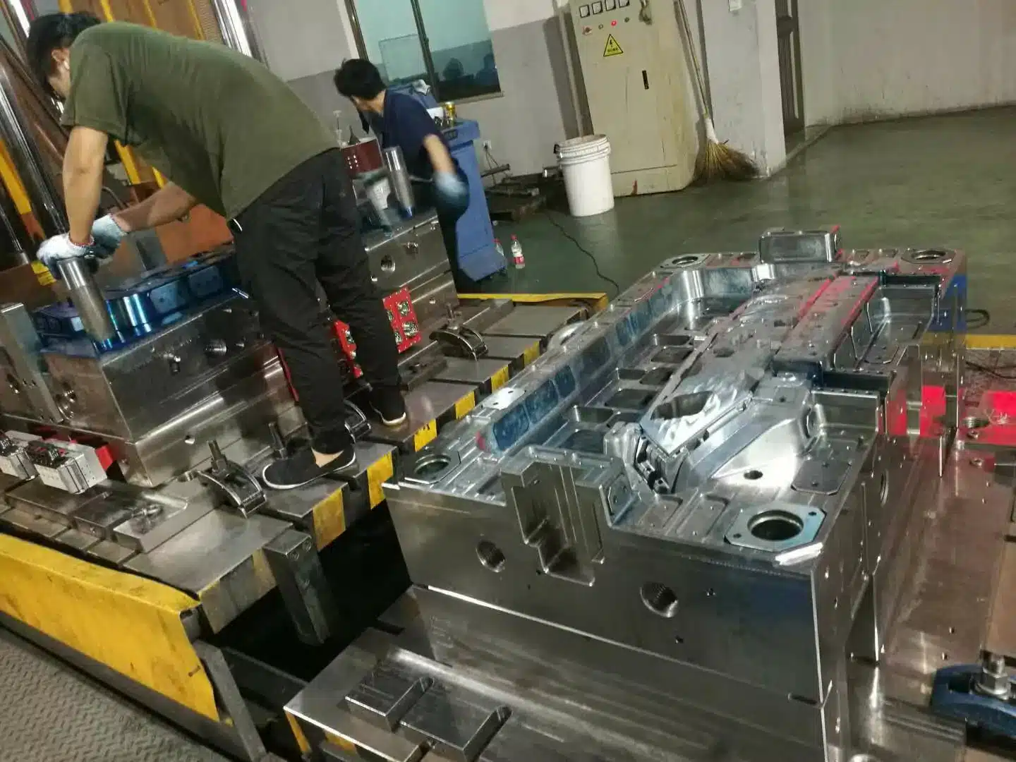

CUSTOM AUTOMOTIVE TOOLING
Automotive Bumper Mould — A Complete Buyer’s Guide
Tooling for a complex automotive bumper typically runs in the $50,000–$100,000+ range and takes 4–8 weeks to design and build. The hard part isn’t finding a manufacturer — it’s vetting one that can hold a Class-A surface, protect your IP, and deliver consistently. This guide walks through specs, real cost drivers, lead times, and a procurement checklist you can use today.
What Is an Automotive Bumper Mould?
An automotive bumper mould is a large injection-molding tool — usually machined from hardened steel — that shapes molten plastic into a finished bumper cover. It’s worth separating two terms that buyers (and a lot of supplier websites) constantly mix up: the bumper is the part on the car, while the bumper mould is the expensive tool that produces that part, thousands of times over.
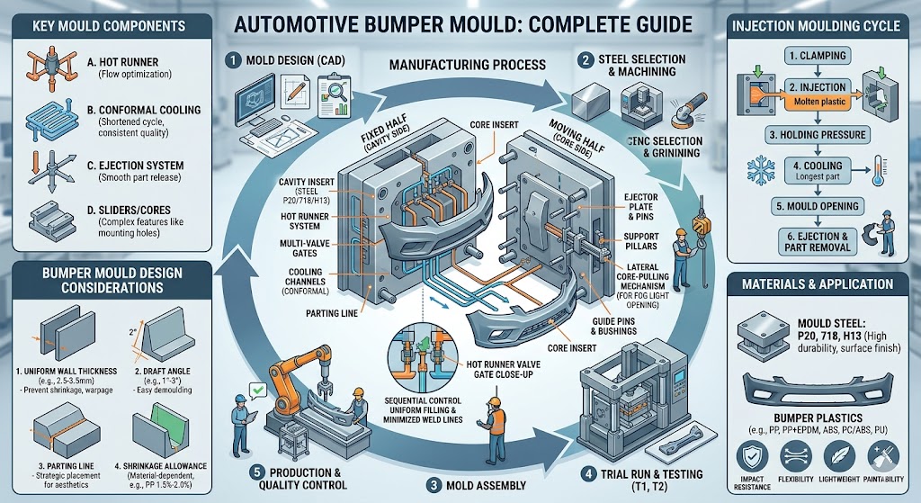
Bumper moulds are among the harder automotive tools to build well. The part is a large, thin-walled, Class-A appearance surface with a deep draw, tight tolerances, and often complex undercuts for clips, sensor housings, and grille openings. That combination is exactly why supplier capability varies so much — and why this guide spends as much time on how to choose a manufacturer as it does on the tooling itself.
Bumper Mould Materials & Steel Grades
There are really two material questions hiding inside “what is a bumper mould made of?”, and they’re easy to conflate. One is the resin that becomes the bumper. The other is the steel that the mould itself is cut from.
The bumper resin
Most production bumpers are injection-molded from polypropylene-based compounds. The most common automotive formulation is PP+EPDM-T20: polypropylene as the base, EPDM rubber to add elasticity and impact resistance, and roughly 20% talc to improve rigidity. For appearance-critical or higher-strength applications, PC/ABS blends are used. Low-volume or specialty bumpers are sometimes produced by reaction injection molding (RIM) using polyurethane instead.
| Resin | Key properties | Typical use | Relative cost |
|---|---|---|---|
| PP + EPDM-T20 | Good flow, impact-resistant, lightweight, recyclable. Wall thickness 1.2–3.0 mm typical. | Mainstream front/rear bumper covers | Low |
| PC / ABS | Higher strength & surface quality, better heat resistance. Wall thickness 1.5–3.0 mm typical. | Premium or appearance-critical parts | Medium |
| Polyurethane (RIM) | Complex geometry, low tooling cost, lower volume | Specialty / low-volume bumpers | Low tooling, higher per-part |
Key resin processing parameters
For the two most common bumper resins, the injection moulding window looks like this:
| Parameter | PP (bumper grade) | PC/ABS |
|---|---|---|
| Drying | Usually not required (hydrophobic) | 80 °C / 2–3 h |
| Melt temperature | ~200–260 °C | 250–280 °C |
| Mould temperature | 20–60 °C | 60–80 °C |
| Back pressure | ~5–10 MPa | 5–12 MPa |
| Shot utilization | 20–80 % of machine max (engineering resins 30–50 %) | |
| Cushion | ~5–10 % of shot stroke | |
The mould steel
This is where most competitor pages go silent — and where a real manufacturer proves expertise. The steel grade directly determines how many parts the mould can produce before it wears out (its “tooling life”). Pre-hardened steels are cheaper and faster to machine; fully hardened steels last far longer and hold a better surface finish for Class-A bumpers. For a deeper look at how steel selection affects long-term tool performance, see our guide on mould steel grades and selection.
| Mould steel | Hardness (HRC) | Approx. tooling life | Best for |
|---|---|---|---|
| P20 / 1.2311 | 28–32 HRC (pre-hardened) | Lower-volume runs | Prototype & short-run bumper tools, general structural parts |
| 2738 (P20+Ni) | 30–36 HRC (pre-hardened, large section) | Medium volume, large moulds | Large-format bumper tools with thick mould plates |
| NAK80 | 38–42 HRC (age-hardened, uniform) | High volume, fine finish | Class-A appearance surfaces, texture detail, easy weld repair |
| S136 (stainless) | 48–54 HRC (Q+T) | Very high volume, corrosive resins | Mirror/transparent parts, humid environments, food-grade |
| H13 / 1.2344 | 44–50 HRC (Q+T, common range) | Very high volume, abrasive resins | GF-filled bumper parts, hot-runner zones, high-wear inserts |
DFM — Design for Manufacturability Key Numbers
A good DFM review translates directly into fewer trial iterations, less warpage, and better surface quality. The table below captures the most-referenced benchmark values used on bumper-class injection moulded parts. For a comprehensive overview of DFM principles across all part geometries, see our in-depth article on Design for Manufacturability in injection molding.
Wall thickness
| Resin | Recommended wall thickness | Notes |
|---|---|---|
| PP (bumper) | 1.2–3.0 mm | Thin walls fill fast; keep variation within ±25 % of nominal |
| ABS | 1.2–3.5 mm | |
| PC | 1.0–3.0 mm (transparent ~2.0 mm) | |
| PC/ABS | 1.5–3.0 mm | |
| PA66 GF | 1.5–3.0 mm | Gate cross-section ~10 % larger than unfilled grades |
| General | 0.8–3.0 mm | Wall-to-wall variation: ≤ ±25 % of nominal within one part |
Draft angles
| Surface type | Draft angle |
|---|---|
| General exterior | 0.5–1° |
| Deep cavity interior | 1–2° |
| High-gloss / mirror | 0.25–0.5° |
| Textured / grained surface | 1–3° (coarser texture = more draft) |
| Rib sides | 0.5–1.5° |
| Boss outer wall | 0.5–1.5° |
| Boss inner bore | ~0.5° |
Ribs & bosses
| Feature | Design guideline |
|---|---|
| Rib thickness | 0.4–0.6 × base wall (50–60 % is typical) |
| Rib height | ≤ 2.5–3 × base wall |
| Rib spacing | ≥ 2 × wall thickness |
| Rib root radius | R ≈ 0.25–0.4 × wall thickness |
| Boss outer wall thickness | 0.4–0.6 × surrounding wall |
| Boss base wall thickness | 0.7–0.9 × nominal wall |
| Boss root radius | R ≈ 0.25 × wall thickness |
| Boss bore depth | ≤ 2.5–3 × bore diameter |
| Internal corner radius | R ≥ 0.25–0.5 × wall thickness |
Gate & Runner System
For a large bumper, gate selection and positioning are the single biggest levers for controlling fill balance, weld-line location, and sink marks on Class-A surfaces.
Runner dimensions (cold runner)
| Element | Typical size | Notes |
|---|---|---|
| Sprue diameter | 4–8 mm (small–medium tools); up to 10 mm large tools | Sprue must not freeze before gate |
| Runner diameter | 4–7 mm (slightly smaller than sprue) | Full-round or trapezoidal preferred |
| Cold slug well volume | 1–2 × cross-section volume of adjacent runner | At sprue base, runner turns, gate front |
Gate size reference by type
| Gate type | Key dimension | Typical range | Notes |
|---|---|---|---|
| Pin-point (cold runner) | Diameter d | Small part: 0.8–1.5 mm; large part: 1.5–2.5 mm | Cone angle 15–30°; land 0.5–1.5 mm |
| Edge/side gate | Depth h × width b | h ≈ 0.5–0.75 × wall; b ≈ 1.5–5 mm (often 2–3 × h) | Land L: 0.7–1.5 mm; keep as short as possible |
| Fan gate | Thickness h × width B | h ≈ 0.5–0.8 × wall; B 4–30 mm depending on part width | Land L 0.7–2 mm; good for thin flat bumper sections |
| Submarine / tunnel gate | Diameter d | 0.8–1.5 mm small; 1.5–2.2 mm large | Tunnel angle 30–60° (35–45° typical); auto-trims on ejection |
| Direct / sprue gate | Diameter | 3–6 mm (≤ sprue root diameter) | R 0.5–1.5 mm transition to part; thick large parts only |
| Ring / film gate | Thickness | 0.3–0.8 mm, full perimeter | Cylindrical parts, eliminates weld lines |
Gate sizing by wall thickness (edge gate & pin-point combined reference)
| Wall thickness T (mm) | Edge gate depth h (mm) | Edge gate width b (mm) | Pin-point diameter d (mm) | Gate land L (mm) |
|---|---|---|---|---|
| < 0.8 | ≈ 0.5 | ≈ 1.0 | 0.8–1.3 | 1.0 |
| 0.8–1.5 | 0.6–0.8 | 1.0–1.5 | 0.8–1.5 | 1.0–1.2 |
| 1.5–2.5 | 0.8–1.2 | 1.5–2.5 | 1.0–1.8 | 1.0–1.5 |
| 2.5–4.0 | 1.2–2.0 | 2.5–4.0 | 1.5–2.2 | 1.2–1.8 |
| > 4.0 | 2.0+ | 4.0+ | 2.0–2.8 | 1.5–2.0 |
Cooling System Design
Cooling time accounts for 50–70 % of the total injection cycle. Getting it right on a large bumper tool is critical for both cycle time and part flatness. Our detailed guide on injection mold cooling system design covers channel layout strategies and coolant flow calculations in full.
Cooling channel geometry
| Parameter | Guideline |
|---|---|
| Channel diameter d | φ 8–14 mm; small tools 6–10 mm, large tools 10–14 mm |
| Channel centre → cavity surface (a) | 1.5–2.0 × d; typically 15–20 mm for φ10 mm channels |
| Channel centre-to-centre spacing (s) | 3–5 × d; typically 30–50 mm for φ10 mm (common 40–60 mm) |
| Channel → mould edge | ≥ 8–10 mm steel remaining |
| Channel → ejector / core pin / screw | ≥ 3–5 mm clearance |
| Inlet fitting → mould face | ≥ 26 mm (standard fitting clearance) |
Cooling channel layout by part wall thickness
| Wall thickness T (mm) | Channel diameter d (mm) | Surface distance a (mm) | Channel pitch s (mm) |
|---|---|---|---|
| 1–2 | 6–8 | 10–15 | 30–40 |
| 2–4 | 8–10 | 15–20 | 40–60 |
| 4–6 | 10–12 | 18–25 | 50–70 |
| > 6 | 12–14 | 20–30 | 60–80 |
Coolant flow & temperature
| Parameter | Target value |
|---|---|
| Flow rate per circuit | 10–60 L/min; commonly 15–30 L/min/circuit |
| Flow velocity (for turbulent Re ≥ 10,000) | 0.5–2.0 m/s; ≥ 0.8–1.0 m/s in small-diameter channels |
| Inlet–outlet ΔT | 2–4 °C; must not exceed 5 °C (wider ΔT = uneven cooling) |
| Coolant temp below mould setpoint | 5–10 °C lower than target mould temperature |
Typical mould temperatures & cooling times
| Resin | Mould temp (°C) | Flow per circuit (L/min) | Cooling time ref. (3 mm wall, s) |
|---|---|---|---|
| PP (bumper) | 40–60 | 15–25 | 15–20 |
| ABS | 50–70 | 20–30 | 18–25 |
| PC | 80–110 | 20–30 | 25–35 |
| PA66 GF | 60–90 | 20–30 | 20–30 |
Ejection System
Bumper covers are large and thin — ejection strategy directly affects whether the part distorts, leaves witness marks on Class-A surfaces, or tears on complex undercuts.
| Feature | Guideline |
|---|---|
| Ejector pin preferred locations | Behind ribs, non-appearance faces, reinforced areas; symmetric distribution |
| Ejector stroke | Full clear of core face + 1–2 mm safety margin |
| Pin slenderness | Control L/D ratio; add guide bushings or increase diameter if excessive |
| Ejector → cooling channel / screw clearance | ≥ 3–5 mm |
| Large flat thin-wall panels | Prefer stripper plate over concentrated ejector pins |
| Appearance-sensitive parts | Air-assist ejection avoids pin witness marks entirely |
Venting
Bumpers have large projected areas and long flow paths — trapped gas burns and short shots are common failures when venting is under-designed. The fundamentals of mould venting explains why vent placement is as important as vent dimensions.
| Parameter | Guideline |
|---|---|
| Vent depth (cavity land) | 0.02–0.05 mm (higher viscosity resins toward upper limit) |
| Vent width | 3–12 mm; typically 3.2–12.7 mm |
| Vent land width (cavity-side flat) | ~1.5 mm (min 3.2 mm, max 6.4 mm for perimeter vents) |
| Priority locations | Opposite gate, flow end, runner tails, cold slug wells, thin-wall convergence zones |
How a Bumper Mould Is Made — The Manufacturing Process
A bumper mould moves through design, machining, trial, and tuning before it ever produces a saleable part. Skipping or rushing the trial stage is the most common cause of late projects.
Design & DFM → CNC machining → EDM → First trial (T0/T1) → Tuning & rework → Approval & shipment
Design & DFM (Design for Manufacturability)
It starts with your 3D CAD data or a physical sample. A capable supplier runs CAD/CAM/CAE and mould-flow analysis to predict how the resin fills the cavity, where it might warp, and where sink marks or weld lines could appear on the visible surface. Decisions made here — wall thickness, draft angles, gate location, parting line — lock in most of the part’s final quality.
Injection molding vs. RIM
| Factor | Injection molding | Reaction injection molding (RIM) |
|---|---|---|
| Volume | High (tens of thousands+) | Low (up to ~1,000 parts) |
| Material | PP, PP+EPDM, PC/ABS | Polyurethane (isocyanate + polyol) |
| Cycle time | Seconds per part | ~1–3 minutes per part |
| Tooling cost | Higher upfront | Lower upfront |
| Best for | Mass-production bumpers | Specialty, large or low-volume parts |
Key bumper mould design features
- Inner vs. outer parting surface: An inner (hidden) parting line keeps the seam off the visible face of the bumper. This is a hallmark of a properly engineered appearance tool.
- Hot runner systems: Multiple controlled gate drops fill a large bumper evenly and reduce waste — critical given the part’s size.
- Gas-assist injection: Helps form large, thin-walled sections without sink marks or warping.
- Sliders & lifters: Required to form undercuts around clips, grille openings, and sensor mounts, then release the part cleanly.
Tolerances — Mould & Part
| Category | Typical tolerance |
|---|---|
| Moulded part (general) | ±0.05–±0.25 mm (commercial to precision grade) |
| ABS/PC-ABS flatness (0–100 mm span) | Commercial ~0.38 mm; precision ~0.25 mm |
| Cavity / core dimensions | ±0.05–±0.25 mm depending on resin shrinkage band |
| Critical inserts & fits | ±0.01–±0.05 mm |
| Ejector pin location & guide clearances | ±0.02 mm typical |
How Much Does a Bumper Mould Cost?
This is the question every supplier site avoids — so here’s a straight answer. Injection mould tooling spans a wide range, from a few thousand dollars for simple parts up to $100,000 or more for complex, multi-cavity, hardened-steel automotive tooling. Because a bumper is large, thin-walled, appearance-critical, and full of undercuts, a complete bumper mould generally sits at the upper end of that range — commonly the $50,000–$100,000+ band for a production-grade tool, with simpler or smaller tools costing less. For a full breakdown of what drives injection mold pricing, see our comprehensive guide to injection molding costs.
The 6 cost drivers
- Part size: A full bumper is one of the largest plastic parts on a vehicle — bigger tool, bigger price.
- Cavity count: A single-cavity tool is cheaper to build; multi-cavity or family tools cost more upfront but slash per-part cost at volume.
- Steel grade: H13 or S136 at 48–52 HRC for long tooling life costs significantly more than P20 at 28–32 HRC.
- Side-actions (sliders/lifters): Every undercut adds mechanism and cost.
- Hot runner system: Adds upfront cost but improves quality and reduces waste.
- Surface finish & texture: A polished Class-A or grained surface adds finishing labor; textured surfaces require larger draft angles (1–3°). See our overview of injection molding surface finishes for SPI grade comparisons.
Clamping force estimation
As a quick sanity check: Clamping force ≈ cavity pressure × projected part area × safety factor (1.1–1.3). A large bumper with a high projected area demands a correspondingly large press — this is one reason capability screening on press tonnage matters.
Lead Time — What to Realistically Expect
Designing and building a bumper mould typically takes 4 to 8 weeks, depending on the complexity of the design, the size of the mould, the number of cavities, and any custom textures or finishes required. The build moves through predictable phases:
- Design & DFM — CAD, mould-flow analysis, sign-off
- Machining — CNC milling and EDM of the cavity and core
- First trial (T0/T1) — the mould runs its first sample parts
- Tuning & rework — dimensions, surface, and fit are corrected
- Approval & shipment — sample approval, then delivery
The phase buyers most often under-budget is trial and rework. Build in time for at least one or two trial-and-tuning iterations; a quoted lead time that assumes a perfect first shot is optimistic.
How to Choose a Bumper Mould Manufacturer
This is the part almost no supplier website helps you with — and it’s where most sourcing mistakes happen. Use the checklist below to qualify any prospective manufacturer before you commit. For a broader sourcing framework, our guide on injection mold manufacturing: China vs US vs Japan compares capability, cost, and risk across regions.
Capability red flags
- Can they show past bumper projects specifically — not just “automotive moulds” in general?
- What is their maximum mould size and press tonnage? A bumper needs a large machine.
- Do they have in-house 5-axis CNC and EDM, or do they subcontract the critical work?
- Do they own a trial press to run T0 samples before shipping the tool to you?
Quality systems
- Are they certified to ISO 9001 — and ideally IATF 16949 for automotive?
- Can they provide traceable QC documentation and CMM inspection reports? (Critical fits: ±0.01–0.05 mm; pin locations: ±0.02 mm)
- Will they share the 2D and 3D drawings of both the part and the mould on delivery?
IP, contracts & risk
- Will they sign an NDA, and is mould ownership explicitly written into the contract?
- Is there accountability for rework, repair, and replacement if defects appear later?
- Can you start with 1–2 moulds as a trial before committing to a large order?
- Have you padded their lead-time estimate to account for realistic production delays?
Why Choose Topworks
- Experience: 20 years building automotive moulds; 18+ bumper moulds delivered.
- Capacity: Maximum mould size 2500 × 1800 mm; presses up to 2800 tons; 5-axis CNC machines.
- Quality: ISO 9001 / IATF 16949 certified; full CMM inspection with traceable reports; critical tolerances held to ±0.01–0.02 mm.
- Steel expertise: We quote steel grade, HRC, and guaranteed shot life on every tool — P20 (28–32 HRC) for prototypes through H13/S136 (48–52 HRC) for high-volume Class-A production.
- Clients: Serving [OEM / Tier-1 / aftermarket] customers in [regions].
Get a free DFM analysis & quote
Upload your 3D CAD or send a sample — we’ll review feasibility and give you a real price and lead time.
Frequently Asked Questions
What material is used for a car bumper mould?
Two materials matter. The bumper itself is usually moulded from PP+EPDM-T20 (polypropylene with EPDM rubber and ~20 % talc) or PC/ABS for premium parts. The mould that forms it is machined from steel — pre-hardened grades like P20 (28–32 HRC) for medium volume, 2738 (30–36 HRC) for large moulds, NAK80 (38–42 HRC) for Class-A appearance, or hardened H13/S136 (44–54 HRC) for very long production runs.
How much does an automotive bumper mould cost?
Complex automotive tooling commonly runs from $50,000 to $100,000+, and a large, appearance-critical bumper mould typically sits at the upper end. The exact price depends on size, cavity count, steel grade, side-actions, and surface finish. A real quote requires your CAD data.
How long does it take to make a bumper mould?
Designing and building a bumper mould usually takes 4 to 8 weeks, depending on complexity, size, cavity count, and texture requirements. Always allow extra time for trial runs and tuning before final approval.
What is the difference between injection molding and RIM for bumpers?
Injection molding suits high-volume production using PP-based resins with cycle times of seconds per part. Reaction injection molding (RIM) uses polyurethane, has lower tooling cost, and suits low-volume runs of up to about 1,000 parts, with cycle times of a few minutes.
What is inner parting surface technology in a bumper mould?
It places the mould’s parting line on a hidden, non-appearance surface of the bumper. After the bumper is assembled on the car, the seam can’t be seen — a key technique for producing a clean Class-A appearance surface.
How long does a bumper mould last?
Tooling life depends mainly on the mould steel. Pre-hardened P20 at 28–32 HRC suits lower volumes; NAK80 at 38–42 HRC handles high-volume Class-A work; fully hardened H13 or S136 at 44–54 HRC provides the longest life for abrasive or corrosive resins. A good supplier will quote a guaranteed number of shots for the steel grade they use.
Can I get a bumper mould made from my CAD file or a sample?
Yes. Most professional manufacturers build the mould directly from your 3D drawing or a physical sample, and return the 2D and 3D drawings of both the part and the mould on delivery.
What draft angle is needed for a textured bumper surface?
Textured or grained surfaces require 1–3° of draft — the coarser the texture, the more draft is needed to avoid drag marks during ejection. High-gloss mirror surfaces conversely need only 0.25–0.5°, combined with a well-polished steel and controlled ejection force.
How is cooling designed for a large bumper mould?
Cooling channels are typically φ8–14 mm in diameter, positioned 1.5–2× the channel diameter from the cavity surface, with a centre-to-centre pitch of 3–5× the channel diameter. Coolant flow is set for turbulent conditions (Re ≥ 10,000; velocity 0.8–2.0 m/s) with an inlet-to-outlet temperature rise of no more than 4–5 °C. Cooling time makes up 50–70 % of the total cycle, so it’s the primary target for optimisation.
Next step
A bumper mould is one of the largest, most demanding tools in plastic injection molding — and the gap between a cheap quote and a tool that actually produces sellable bumpers for 500,000 shots is enormous. If you have CAD data or a reference sample, send it over and we’ll come back with a DFM review, steel-grade recommendation, and a realistic price and lead time.

