
Can AI Replace Moldflow?
AI cannot fully replace Moldflow for production-grade injection molding decisions, but in 2026 AI is a fast, low-cost first-pass DFM screener that helps buyers reduce mold revisions before paying for full Moldflow simulation.
Introduction
If you are sourcing an injection mold in the United States and someone has pitched you an “AI mold analysis” tool, you are probably asking the same question every procurement engineer asks in 2026: Can AI Replace Moldflow? What Buyers Should Know Before Mold Design is now a real budget conversation, not a research paper. This guide is written for U.S. mechanical, plastics, and manufacturing engineers who specify molds, sign off on DFM reports, or approve tooling POs from $20,000 prototype molds up to $250,000+ production tools.
You will learn what AI tools can and cannot do, where Autodesk Moldflow still wins, how engineering judgment fits in, and a practical decision framework you can apply before signing your next mold quote.
What is “Can AI Replace Moldflow? What Buyers Should Know Before Mold Design”?
This is a buyer-side decision framework that compares AI-based plastic part screening tools to validated injection-molding simulation (Autodesk Moldflow / Moldex3D / SIGMASOFT) so engineers can choose the right verification depth for the right stage of mold design. It treats AI and Moldflow not as competitors, but as tools sitting at different points on the risk-cost curve. The framework helps buyers avoid two expensive mistakes: paying for full simulation on parts that don’t need it, and skipping simulation on parts that absolutely do.
Key facts:
- AI tools today are best at early-stage DFM screening (wall thickness, draft, undercuts, gate suggestions).
- Moldflow remains the industry-validated solver for warpage, fiber orientation, weld lines, and pressure prediction.
- Most U.S. tier-1 suppliers (automotive, medical, aerospace) still require Moldflow or equivalent reports for PPAP and design freeze.
- AI can cut early iteration time, but does not replace a credentialed engineer’s sign-off.
Why This Matters in 2026 for U.S. Engineers
The mold design stack has changed: AI is now a real layer, not a marketing slide. In the last 24 months, tools like Autodesk Fusion’s generative DFM, PartCloud, Plasmatech AI, and several China-based “instant DFM” platforms have entered U.S. supply chains. At the same time, Autodesk Moldflow Insight 2026 added more automation and machine-learning-assisted meshing — meaning the line between “AI” and “simulation” is blurring inside the legacy tools too.
For a U.S. buyer, the practical impact is: you are now being quoted molds where the supplier’s “DFM analysis” might be an AI screenshot, a full Moldflow study, or something in between. You need to know which one you actually got.
AI vs Moldflow vs Engineer Judgment: What Each One Actually Does
Each layer answers a different question.
| Layer | Primary Question Answered | Typical Output | Trust Level for Production |
|---|---|---|---|
| AI DFM tools | “Is this part roughly moldable?” | Wall-thickness heatmap, draft warnings, gate suggestions | Low–Medium (screening only) |
| Autodesk Moldflow / Moldex3D | “Will this part fill, pack, cool, and warp acceptably?” | Fill time, pressure, weld lines, warpage in mm | High (industry standard) |
| Experienced mold engineer | “Will this part actually run on my press, with my resin lot, on my tool steel?” | DFM report, gate/runner strategy, steel safe areas | Highest (final accountability) |
The biggest mistake U.S. buyers make is treating these three layers as substitutes instead of a stack.
Where AI Genuinely Helps Before Mold Design
AI is strongest when the question is geometric, repetitive, and visual. Understanding Design for Manufacturability (DFM) in injection molding is essential context before relying on any AI tool.
- Wall thickness analysis — AI flags thin/thick zones in seconds, often as well as Moldflow’s thickness tool. Industry DFM benchmarks: general wall thickness 0.8–3.0 mm; by resin: PP 1.2–3.0 mm, ABS 1.2–3.5 mm, PC 1.0–3.0 mm, PC/ABS 1.5–3.0 mm, PA66 GF 1.5–3.0 mm. Wall thickness variation within a single part should stay within ±25% of nominal thickness.
- Draft angle checking — Reliable for standard pull directions; weaker on side actions and lifters. Typical draft guidelines: standard exterior surfaces 0.5–1°, deep cavity interiors 1–2°, textured/grained surfaces 1–3°, high-gloss/mirror surfaces 0.25–0.5°, rib sidewalls 0.5–1.5°.
- Undercut and parting-line suggestions — Useful first pass, but human review required for complex tools. Parting lines should be kept off sealing faces, O-ring grooves, and high-gloss decorative surfaces; where parting lines must cross visible areas, design them into natural break lines, chamfers, or steps.
- Gate location proposals — Reasonable starting points; AI cannot yet predict balanced multi-cavity flow. Gate thickness should start at approximately 0.5–0.75× local wall thickness; for glass-fiber-filled materials, increase gate cross-section by roughly 10% versus unfilled grades to reduce shear.
- Cost estimation and tonnage estimation — Increasingly accurate for commodity resins (ABS, PP, PC, PA6). Clamp force estimate: clamp force ≈ melt pressure × projected part area × safety factor (safety factor ≈ 1.1–1.3).
- Resin substitution screening — Some tools cross-reference Campus or UL Prospector data to flag obvious mismatches.
For a U.S. engineer reviewing a quote in a Tuesday morning meeting, an AI DFM check is a reasonable gate before sending the file to a Moldflow analyst.
Where Moldflow Still Wins (and Probably Will Through This Decade)
Moldflow wins anywhere physics, validated material cards, and regulatory traceability matter. For a deeper look at when simulation is truly mandatory versus optional, see our guide on Moldflow analysis: when it’s mandatory and when to skip.
- Warpage prediction with fiber-filled materials (30% glass-filled PA, PBT, PPS) — rib height should be ≤ 2.5–3× wall thickness, rib thickness 0.4–0.6× wall thickness, and rib layout as symmetric as possible; AI cannot yet model the anisotropic shrinkage these rules are designed to control.
- Weld-line strength estimation for structural and Class-A cosmetic parts.
- Cooling channel optimization with conformal cooling and pressure-drop modeling. Standard water-circuit guidelines: channel diameter φ8–14 mm (typically 8–10 mm for small/medium molds, 12–16 mm for large molds); channel centerline to cavity surface 1.5–2× channel diameter (≈15–20 mm for φ10 mm channels); channel center-to-center spacing 3–5× channel diameter (≈30–50 mm for φ10 mm); minimum clearance from ejector pins, screws, and other features ≥ 3–5 mm; cooling inlet/outlet fittings should maintain ≥ 26 mm from mold edge. Per-circuit flow rate 15–30 L/min, inlet-to-outlet temperature rise ΔT ≤ 4–5 °C; Re ≥ 10,000 (turbulent) is required for effective heat transfer, corresponding to flow velocity ≈ 0.5–2.0 m/s.
- Pack and hold profile development for tight-tolerance medical and optical parts.
- PPAP and Tier-1 documentation — Ford, GM, Stellantis, Boeing, and most medical OEMs explicitly accept Moldflow output as a validated source.
- Material database depth — Autodesk’s Moldflow material database contains thousands of characterized resins with measured PVT, viscosity, and thermal data, something no current general-purpose AI tool reproduces.
According to Autodesk’s official Moldflow documentation, the solver is built on validated rheological models (Cross-WLF, Tait PVT) that have been benchmarked against physical molding trials for over three decades. AI tools, as of 2026, do not publish equivalent validation data.
Can AI Replace Moldflow? The Honest Answer
No, AI cannot replace Moldflow in 2026 for production tooling decisions, but yes, AI can replace the first 60–70% of low-stakes geometric DFM checks that engineers used to do manually.
Think of it the way structural engineers think about hand calculations vs. FEA: hand calcs (and now AI) screen out the obvious, but you still run FEA (and Moldflow) before you cut steel on anything that matters. The question is not “AI or Moldflow” — it is “which parts deserve which level of analysis.” For more on how AI is reshaping this process, see our article on AI-driven mold flow analysis: beyond simulation to prediction.
A defensible 2026 split for a U.S. buyer:
- AI-only is acceptable for: prototype molds, low-volume aluminum tools, non-critical commodity parts, and early concept screening.
- Moldflow is required for: any safety-critical part, any cosmetic Class-A surface, any glass-filled or fiber-reinforced resin, any tight-tolerance medical or optical part, and anything tied to PPAP or 21 CFR Part 820.
- Both, in sequence, is best for: mid-volume consumer products and industrial enclosures, where AI cuts iteration cost and Moldflow finalizes the design.
A 7-Step Decision Process Before You Approve a Mold
Use this sequence on your next mold PO.
- Define the part class. Is it safety-critical, cosmetic, structural, or commodity? This sets your minimum analysis bar.
- Run AI DFM first. Use a tool like Autodesk Fusion’s DFM, your supplier’s AI report, or an independent platform. Total time: minutes.
- Lock the resin and grade. Not just “PC” — specify “Covestro Makrolon 2407” or equivalent with a datasheet. Processing conditions vary significantly: ABS requires drying at ~80 °C for ~1.5 h, mold temperature 45–80 °C, melt temperature 190–235 °C; PC requires drying at 90–110 °C for ≥ 2 h, mold temperature 80–110 °C, melt temperature 280–320 °C; PC/ABS requires drying at 80 °C for 2–3 h, mold temperature 60–80 °C, melt temperature 250–280 °C.
- Decide if Moldflow is required. Use the matrix in the previous section. If in doubt, run it.
- Review the Moldflow report yourself. Look for fill time, max injection pressure (should leave 20%+ machine reserve; shot utilization for engineering resins should be 30–50% of machine maximum), weld-line locations on cosmetic faces, and predicted warpage vs. tolerance. Cushion should be approximately 5–10% of shot stroke.
- Walk the tooling layout with your mold engineer. Confirm gate, runner, cooling, and ejection match what the simulation assumed. Key runner parameters: sprue diameter 4–8 mm for small/medium tools; runner diameter 4–7 mm (slightly smaller than sprue); cold slug wells sized to at least 1–2× the volume of the adjoining runner cross-section; gate land length 0.5–1.0 mm for thin-wall parts, 1.0–1.5 mm for thick-wall parts. Ejector layout: ejection stroke = full part release plus 1–2 mm safety margin; ejector pins/sleeves/cooling circuits/screws must maintain ≥ 3–5 mm clearance from each other.
- Sign off only with a named engineer’s stamp. AI does not carry liability. A PE or a credentialed plastics engineer does.
Common Mistakes U.S. Buyers Make
For a thorough breakdown of defects caused by poor analysis and process setup, see our guide to troubleshooting injection molding product defects.
- Accepting an AI screenshot as a “Moldflow report.” They are not the same; ask explicitly which solver was used.
- Trusting AI gate suggestions on multi-cavity tools. Flow imbalance is still a Moldflow-grade problem. Geometric balancing (equal runner lengths to all cavities) is the starting point; runner diameter fine-tuning — slightly larger diameter to far cavities, slightly smaller to near cavities — requires incremental short-shot testing.
- Skipping cooling analysis. Most warpage issues trace back to cooling, not gating — and AI tools rarely model cooling well. Cooling time is typically 50–70% of total cycle time; it scales roughly with the square of wall thickness (doubling wall thickness quadruples cooling time). Learn more about injection mold cooling systems and best practices.
- Using generic resin assumptions. “PA66” is not a material spec; the grade and fiber loading change everything.
- Believing free-trial AI tools match Moldflow accuracy. They do not, and reputable vendors do not claim they do.
- Ignoring tolerance stack-up. Even a perfect simulation does not catch dimensional issues that come from assembly, not molding. Typical molded part tolerance range: ±0.05–±0.25 mm depending on dimension and resin (commercial vs. precision grade).
- Buying the mold before the DFM is signed off. Cutting steel based on a “we’ll fix it in tuning” promise is the most expensive mistake in this list.
DFM Quick-Reference: Key Experience Values
The table below summarizes the most commonly used engineering benchmarks. These are starting points; always verify against your specific resin datasheet and part geometry. For additional industry benchmarks, Plastics Today’s injection molding resource center provides regularly updated process guidelines from industry practitioners.

Gate Type Selection Reference
Not all gates are equal. The right gate type depends on part geometry, resin, cosmetic requirements, and automation level.
| Gate Type | Typical Dimensions | Best For | Notes |
|---|---|---|---|
| Side (edge) gate | h: 0.5–2.0 mm; w: 1.5–5 mm; L: 0.5–2.0 mm | Most general parts; easy to modify | Most common; h is the most critical dimension |
| Pin (submarine/tunnel) gate | d: 0.8–1.5 mm small parts; 1.5–2.2 mm large parts; angle 35–45° | Auto-degating; cosmetic parts | PC/PMMA: use larger diameter to avoid shear burn |
| Fan gate | h: 0.5–1.5 mm; w: up to 10–30 mm; L: 0.7–2 mm | Wide flat parts; flow balance | Spread flow front evenly |
| Film/diaphragm gate | t: 0.2–0.8 mm; spans full circumference | Round lids, optical parts | Best weld-line and concentricity control |
| Ring gate | t: 0.3–0.8 mm; spans part circumference | Cylindrical parts | Used at part base |
| Direct (sprue) gate | d: 3–6 mm; R at junction 0.5–1.5 mm | Thick large parts, engineering resins | No cold runner waste; gate mark on part |
Resin tendency guide: High-flow resins (PE, PP, PS, ABS) can use the lower end of gate size ranges for faster freeze-off. High-viscosity or shear-sensitive resins (PC, PMMA, PA66+GF) need the upper end of gate size ranges plus minimal land length to avoid pressure drop and burning. Cosmetic, transparent, or mirror-finish parts should favor fan, film, or ring gates to minimize weld lines and shear marks.
Gate cross-section as a proportion of runner: typically 3–9% of runner cross-sectional area. Longer flow paths require larger gates; the general L/T flow-length-to-thickness ratio should stay at or below approximately 150 (e.g., for 1.5 mm wall thickness, limit flow length to ~225 mm before adding a second gate).
Mold Steel Selection Reference
The tool steel matters. AI tools generally do not factor steel selection into their analysis; Moldflow does not either — but your mold engineer must. For more detail on steel grades used in Chinese tooling, see our mold steel selection guide.
| Steel | Type | Typical Hardness | Best Application |
|---|---|---|---|
| P20 (1.2311) | Pre-hardened | ~28–32 HRC | Medium-volume molds, general structural and appearance parts |
| 2738 | Pre-hardened, thick-section | ~30–36 HRC | Large molds, thick cross-sections requiring uniform hardness |
| S136 | Stainless martensitic | Annealed 190–230 HB; working 48–52 HRC | Mirror/optical, transparent, medical, food, corrosive environment |
| NAK80 | Age-hardened pre-hardened | ~38–42 HRC (uniform through cross-section) | High-gloss, mirror, sharp texture, good weldability for rework |
| H13 (1.2344) | Hot-work tool steel | ~44–50 HRC (after hardening) | High-temperature zones, glass-filled resins, hot-runner seats, high-wear inserts |
Mold Manufacturing Tolerance Reference
| Feature | Typical Shop Tolerance |
|---|---|
| General cavity dimension | ±0.05–±0.25 mm |
| Precision inserts / critical fits | ±0.01–±0.05 mm |
| Ejector pin hole position / guide fits | ~±0.02 mm |
| Finished part (commercial grade) | ±0.05–±0.25 mm (dimension-dependent) |
| ABS/PC-ABS flatness 0–100 mm (commercial) | ~0.38 mm |
| ABS/PC-ABS flatness 0–100 mm (precision) | ~0.25 mm |
Venting Reference
Insufficient venting causes burn marks, short shots, and weld-line weakness — problems AI tools may flag geometrically but cannot fully predict without simulation. The Society of Plastics Engineers (SPE) provides extensive technical resources on venting standards and best practices for injection molding.
| Parameter | Recommended Value |
|---|---|
| Vent depth (cavity clearance) | 0.02–0.05 mm |
| Vent width | 3–12 mm |
| Vent land width (adjacent to cavity) | ~1.5 mm (min 3.2 mm, max 6.4 mm for perimeter vents) |
Vent placement priority: opposite the gate, at flow end-fill zones, at runner tails, at cold slug wells, and at thin-wall convergence areas.
Cost and Time Comparison: AI vs Moldflow in a Real Project
| Activity | AI DFM Tool | Autodesk Moldflow Insight |
|---|---|---|
| Setup time | Minutes | Hours to a day |
| Cost per analysis (U.S., 2026) | Free–$200 | $500–$3,000+ per study |
| License cost | Often subscription, $0–$2k/yr | Several thousand to $20k+/yr |
| Required expertise | Junior engineer | Trained simulation analyst |
| Accepted by Tier-1 OEMs | No | Yes |
| Validated against physical trials | Rarely published | Decades of public benchmarks |
Pricing varies by vendor, region, and contract; verify current quotes directly.
How to Brief Your Mold Supplier in 2026
Tell them, in writing:
“Provide a written DFM report. State whether it is AI-generated, Moldflow-generated, or hybrid.”
“If Moldflow is used, send the .sdy or PDF report with fill time, pressure, weld lines, and warpage.”
“Specify the resin grade used in simulation, including fiber content and supplier.”
“List any assumptions about machine tonnage, melt temperature, and cooling time.”
“Include the name and credentials of the engineer signing the report.”
This single paragraph in your RFQ will eliminate most of the “AI vs Moldflow” ambiguity in U.S. mold sourcing. For guidance on sourcing molds from China and what to include in your RFQ, see our resource on buying injection molding from China.
Key Takeaways
- AI cannot replace Moldflow for production-grade injection-mold validation in 2026.
- AI is highly effective as a first-pass DFM screener for geometry, draft, wall thickness, and gate suggestions.
- Autodesk Moldflow remains the de facto standard accepted by U.S. Tier-1 OEMs and required for most PPAP submissions.
- Safety-critical, cosmetic, fiber-filled, and tight-tolerance parts still require validated simulation, not AI screening.
- The smartest 2026 workflow is AI for early screening, Moldflow for verification, and a credentialed engineer for sign-off.
- U.S. buyers should explicitly ask suppliers which solver produced their DFM report.
- Cutting tooling steel before a signed DFM and simulation review is the single most expensive mistake in mold buying.
FAQs
Is AI more accurate than Moldflow for plastic part analysis?
No. AI tools are faster and cheaper but do not match Moldflow’s validated rheological models. AI is best for screening; Moldflow remains the benchmark for production decisions, especially with filled or engineering-grade resins.
How much does a Moldflow analysis cost in the United States in 2026?
A single Moldflow study typically ranges from about $500 for a basic fill analysis to $3,000 or more for a full fill-pack-warp study, depending on part complexity and analyst rates. Many U.S. mold makers include a basic study in the tooling quote; advanced studies are usually billed separately.
Can I skip Moldflow if my supplier uses AI DFM software?
Only for low-risk, low-volume, or prototype parts. For any production tool tied to PPAP, medical, automotive, or aerospace requirements, AI DFM alone is generally not accepted as validation.
What is the difference between Autodesk Moldflow and Moldex3D?
Both are validated injection-molding simulation packages used worldwide. Moldflow is the most common in U.S. automotive and consumer markets, while Moldex3D has strong adoption in Asia and in true 3D fiber-orientation work. Most U.S. Tier-1s accept either.
Will AI eventually replace Moldflow entirely?
Probably not this decade. AI may automate more of Moldflow’s setup and meshing, and Autodesk itself is integrating machine learning into Moldflow Insight, but liability, validation, and OEM acceptance still require physics-based, traceable simulation.
Do I need Moldflow for a prototype mold?
Usually no. For aluminum prototype tools running short series, AI DFM plus an experienced mold engineer is typically sufficient. Save Moldflow budget for the production tool.
Who signs off on a mold design — AI, Moldflow, or the engineer?
A named engineer signs off, always. AI and Moldflow are tools; only a credentialed engineer carries professional and legal accountability for the design.
What should be in a Moldflow report I receive from a supplier?
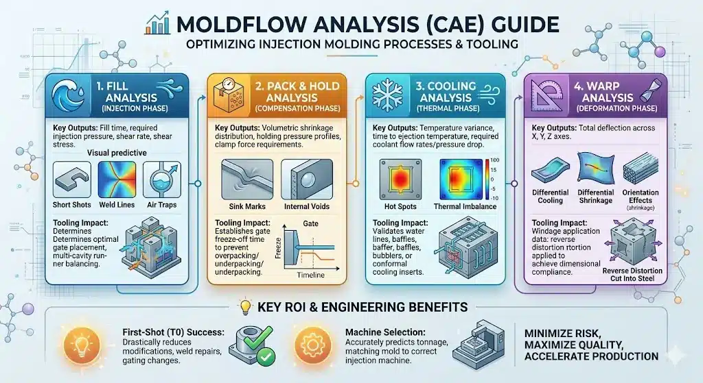
At minimum: fill time, fill pattern, maximum injection pressure, weld-line locations, air-trap locations, cooling time, and predicted warpage. The report should also state the resin grade, machine tonnage assumption, and the analyst’s name.
Conclusion
Can AI Replace Moldflow? What Buyers Should Know Before Mold Design comes down to one sentence: AI is your fast, cheap early-warning system, Moldflow is your validated proof, and a credentialed engineer is the only one who signs.
For U.S. engineers in 2026, the right move is not to pick a side but to layer the tools — AI for the first hour, Moldflow for the critical decisions, and human judgment for everything that gets cut into steel. Apply the 7-step decision process before your next mold PO, demand transparency about which solver produced your DFM report, and you will spend less on revisions and more on parts that actually run.

