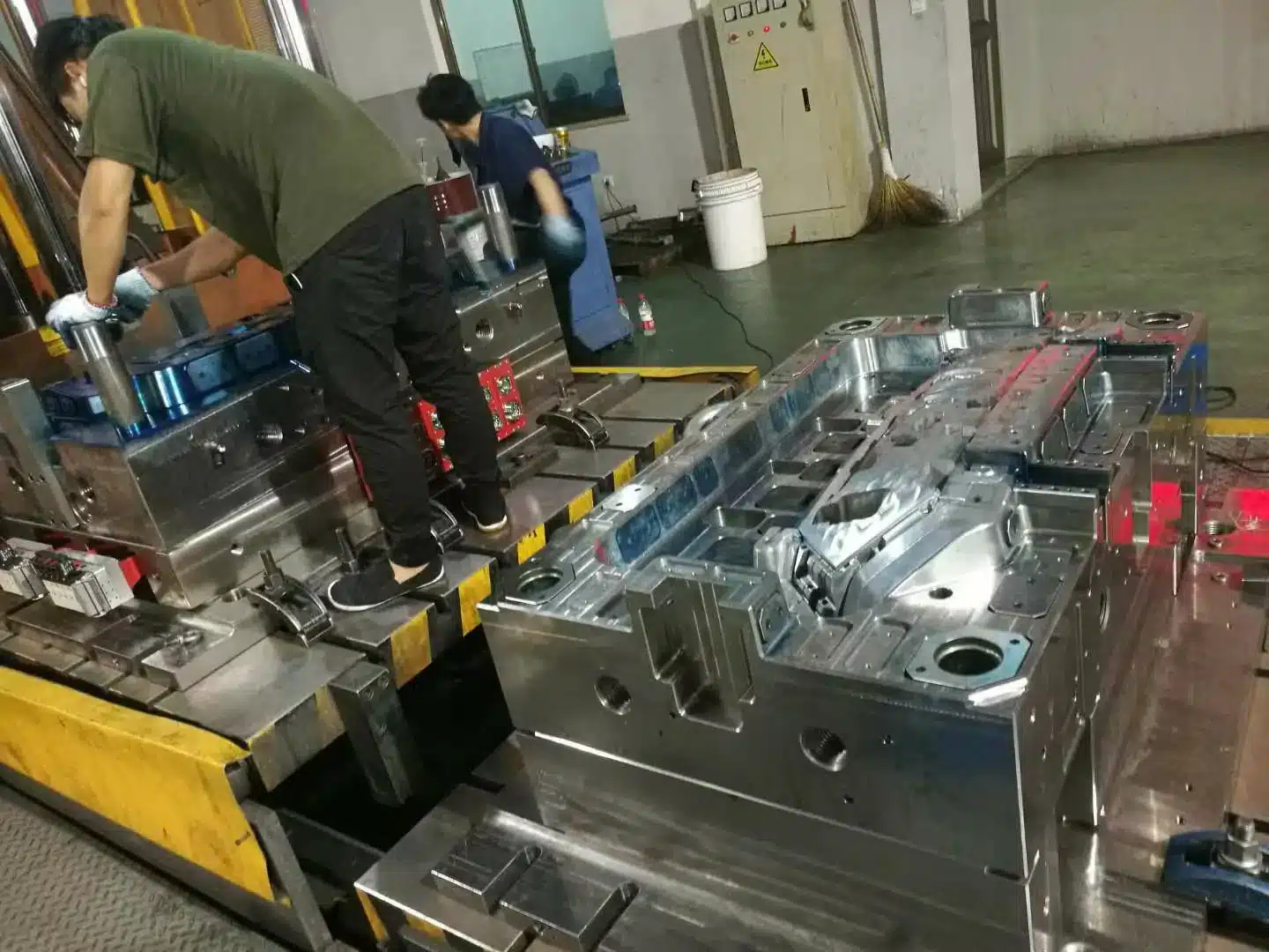

Hot Runner Tooling Engineering
Hot Runner System Design in Plastic Injection Molds
A hot runner system acts as a heated extension of the injection molding machine barrel, delivering molten plastic directly into mold cavities without generating cold runner scrap. Achieving zero-leakage, balanced filling across multi-cavity hot runner molds requires strict control over manifold heat balance, H7/m6 bushing tolerances, and pressure pad preload.
- Specific Heating Capacity: Size manifold heaters between 150 and 300 W/kg; exceeding 300 W/kg causes severe temperature overshoot and thermal degradation.
- Thermal Isolation & Radiation: Temperature differentials between the manifold and clamp plates reach up to 300°C; mount polished aluminum reflector plates to cut radiant heat loss by an order of magnitude vs. oxidized steel.
- Mechanical Fits & Preload: Machine probe shanks and locating bushings to an H7/m6 fit; grind support pads to a single common plane with a 0.05 mm interference preload and keep contact stress below 300 N/mm².
Interactive Mold Structure: Explore how the hot runner manifold, locating bushings, and nozzle probes integrate into the mold assembly:
Main components of a plastic injection mold
- Core and Cavity — form the shape of the plastic part.
- Runner System — guides molten plastic into the cavity.
- Gate — entry point where plastic flows into the part.
- Cooling Channels — cool the plastic quickly and evenly.
- Ejector Pins — push the finished part out of the mold.
- Slider or Lifter — release side holes and undercuts.

Eliminating the cold runner network saves raw resin and reduces the shot volume the screw must plasticize during each cycle. Shortening screw recovery time and eliminating thick runner cooling cuts overall cycle time and boosts press output.
Hot runner molds deliver the highest return on investment in high-cavity tooling, small precision components, and engineering parts that prohibit regrind blending. Converting an existing cold-runner tool to a hot-runner manifold is also a proven way to upgrade press productivity, provided the plant manages the auxiliary temperature controllers and thermal balance.
| Hot Runner Design Parameter | Target Engineering Specification | Consequence of Non-Compliance |
|---|---|---|
| Manifold Heating Density | 150 – 300 W/kg of manifold steel mass | >300 W/kg causes wild temperature swings and resin burning |
| Support Pad Contact Stress | Max 300 N/mm² (hardened tool steel) | Plastic deformation of heated probes/torpedoes and melt leakage |
| Probe & Bushing Fit | H7/m6 precision ground fit (no EDM) | 10 μm gap/insulating layer drops heat transfer by ~10% |
| Pressure Pad Interference | 0.05 mm overall thermal expansion preload | Manifold leakage floods air gap, ruining thermal balance |
| Chimney Convection Loss | Seal open mold sections + polished Al plates | Unsealed air drafts cause up to 60°C nozzle-to-nozzle variance |
Heat Balance Considerations
Inadequate heat balance is the number-one root cause of hot runner system failure in production. External band or wound nozzle heaters fail prematurely if the contact surface area is too small, while cartridge heaters burn out when loose bore tolerances trap an insulating air pocket between the heater sheath and manifold steel.

Embedding tubular heating elements into machined manifold channels using thermally conductive cement provides durable, uniform heat transfer when three assembly rules are followed:
- Avoid entrapped air pockets inside the thermally conductive cement during potting,
- Coat 100% of the tubular heater sheath and channel walls with conductive cement, and
- Follow the manufacturer’s exact thermal curing schedule before applying full electrical load.
Because cured conductive cement is brittle and prone to crumbling under vibration, cover the heater channels with bright cold-rolled or polished aluminum cover plates bolted directly to the manifold.
Maintaining identical melt temperatures at every nozzle probe tip (torpedo)—especially in indirectly heated systems—requires minimizing local temperature gradients across the manifold block:
- Maximize the thermal mass of the manifold steel block,
- Minimize conductive, convective, and radiative heat losses to the surrounding cold mold plates, and
- Use closed-loop PID temperature controllers with soft-start power ramping.
Size manifold heaters to deliver a specific heating capacity between 150 and 300 W/kg of manifold weight. Exceeding 300 W/kg causes severe temperature overshoot and oscillation.
Even advanced PID controllers cannot stabilize a manifold if physical heat losses are ignored. In one four-nozzle hot runner mold, convective air drafts (“chimney effect”) created a 60°C temperature difference across the nozzles, making part tolerances impossible to hold until the open air gaps around the manifold were sealed.
With temperature differentials between the hot manifold and cooled cavity plates reaching 300°C, radiant heat loss rises sharply if manifold surfaces oxidize or rust. Radiant heat transfer between two slightly rusted steel faces is up to ten times higher than between polished aluminum and steel—making polished aluminum radiation shields a low-cost, high-impact upgrade.
Conductive heat loss through support pads and locating bushings is proportional to contact area. Keep support contact areas as small as possible without exceeding the maximum permissible compressive stress of 300 N/mm², and always use hardened steel support pads so the heated probes do not deform under injection load.
Machine the probe shank, locating bushing, and manifold seat to a precision ground H7/m6 fit. Never use electrical discharge machining (EDM) on heater or probe seats: rough EDM surfaces allow melt intrusion, and an insulating gap of just 10 μm reduces heat transfer by roughly 10%.
Multiple Fits (Double Fits)
The hot runner manifold mounts inside the mold cavity plate via pressure support pads and locating bushings. Preventing manifold bending and high-pressure resin leakage requires grinding all support pads on a surface grinder so they seat on a single common reference plane.
Designing two or more stepped seating planes (“double fits”) fails in production because thermal expansion alters the contact area ratio across different planes, creating uneven surface pressures at the nozzle gate seals.
Once molten plastic leaks past a locating bushing into the insulating air gap around the manifold, the higher thermal conductivity of solid plastic (compared to air) drains heat rapidly into the cooled mold plates. If the operator raises manifold temperature to compensate for that heat drain, the resin overheats, degrades thermally, and releases toxic fumes.
Fit pressure pads and locating bushings with an overall interference preload of 0.05 mm (keeping contact pressure under 300 N/mm²) and avoid redundant double fits to guarantee a leak-free thermal seal.
End Plugs
Poorly fitted manifold end plugs cause dead-spot material degradation, slow color changes, and high-pressure melt leaks. Every hot runner manifold end plug must meet four engineering criteria:
- 100% Leakproof Seal: Withstand peak injection and packing pressures at operating temperature,
- Zero Dead Corners: Streamline the melt turn-around channel so resin cannot stagnate and char,
- Anti-Rotation Lock: Mechanically key or pin the plug so thermal cycling cannot loosen the threads, and
- Service Removability: Allow clean extraction for manifold gun-drilling inspection and purge cleaning.
Planning a multi-cavity hot runner mold or troubleshooting manifold leakage and color-change delays? Contact our tooling engineers for a complete hot runner layout review.

