
Robotics & AI Hardware
Insert Molding for Robotics: Metal Where You Need It, Plastic Everywhere Else
Insert molding places a metal part into the mold, then encapsulates it in plastic in one shot. The robot part comes out with metal threads, bearings, or contacts already built in.
This guide covers where insert molding fits a robot, the inserts that matter, and the design rules that keep them from cracking or spinning loose. It expands the robotics & AI hardware overview.
Insert molding for robotics in brief:
- What it is: a metal insert is placed in the mold and encased by plastic in one cycle — “done in one.”
- Common inserts: threaded brass inserts, bearing bushings, electrical contacts, alignment pins.
- Why robots use it: metal-grade threads and bearing surfaces, at plastic weight, with no secondary assembly.
- Design rule: knurl or groove the insert, keep enough plastic around it, round every corner.
What insert molding is
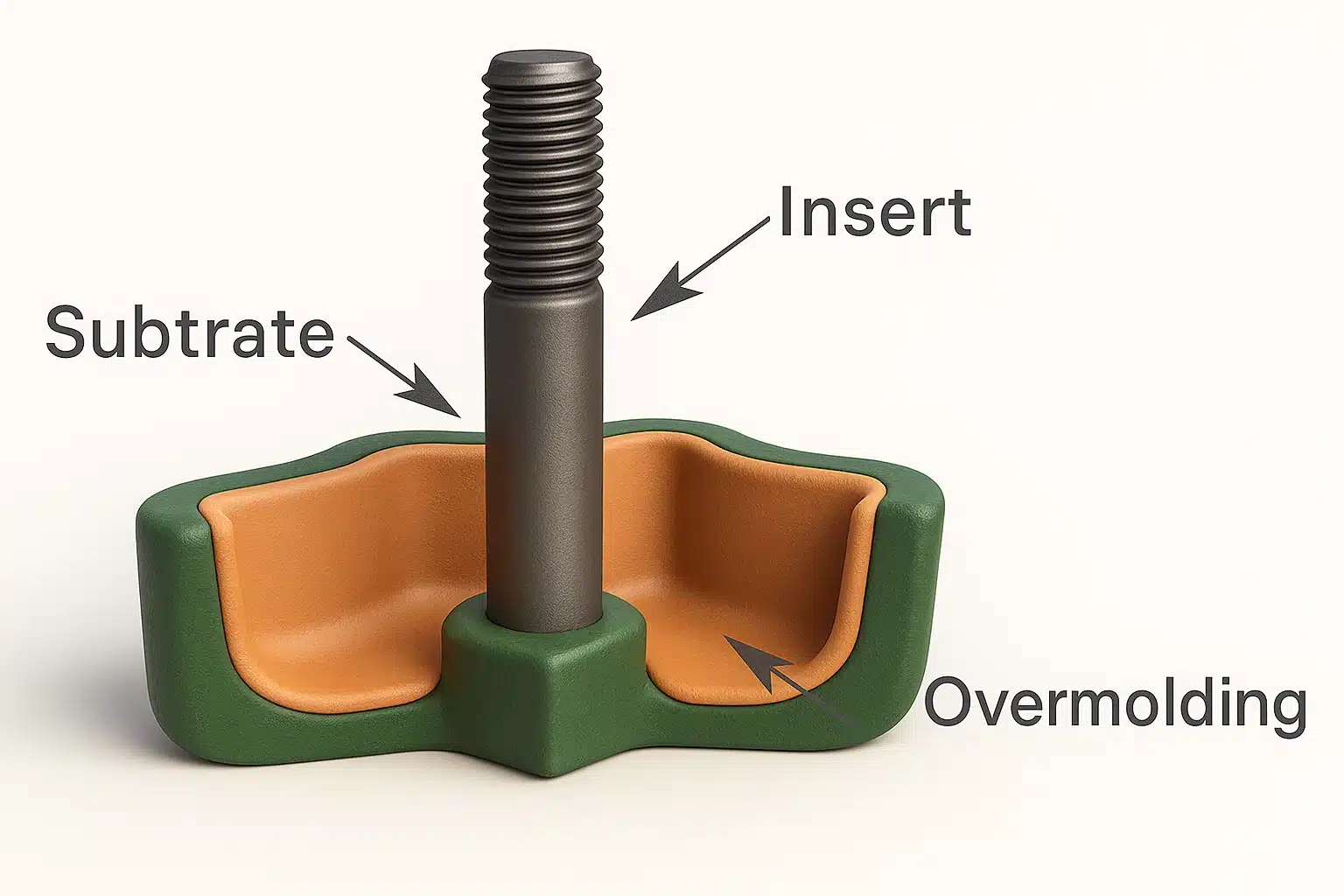
The insert — a threaded bushing, sleeve, bearing, or contact — is set on a core inside the mold. The mold closes, plastic flows around it, the mold opens, and the finished part ejects. The insert is now locked in position, part of the structure.
This differs from overmolding, which is two shots. Insert molding is one shot. For the fundamentals that apply across every industry, see insert molding explained. As the trade saying goes, it is “done in one.” That single cycle is where the cost and reliability gains come from.
Rule of thumb. Any robot part with a threaded hole is worth evaluating for insert molding. So is any plastic part that needs a hard bearing surface or an electrical contact in a specific spot.
Where robots use insert molding
Threaded inserts for assembly
Robots are assembled and serviced with screws. Molding a brass threaded insert into a boss gives metal threads in a plastic part. They hold torque, survive repeated disassembly, and never strip like tapped plastic.
Any cover, bracket, or housing that bolts to a mating piece benefits. Electronics enclosures with bolt-on lids are a classic case.
Bearing seats and bushings
A bronze or brass bushing molded into a rotating part becomes the bearing surface. On a gear, pulley, or joint, this extends life far beyond an unbushed plastic bore. The gearbox housing gets its bearing seats this way.
Electrical contacts and terminals
Sensors and connectors need metal contacts in exact positions. Insert molding fixes terminals and pins during the molding cycle, so alignment holds without a separate placement step.
Alignment pins and compression limiters
Non-threaded sleeves act as pass-throughs or compression limiters, so a bolt can be torqued without crushing the plastic. Pins set precise mating alignment between assembled parts.
Insert materials
| Insert metal | Why chosen | Typical robot use |
|---|---|---|
| Brass | Machinable, corrosion-resistant, stable torque | Threaded inserts in covers and brackets |
| Stainless steel | High strength, corrosion resistance | Structural or wash-down environments |
| Carbon steel | Cost-sensitive structural parts | Internal load points, low corrosion risk |
| Bronze / brass bushing | Bearing surface, wear resistance | Rotating joints, gears, pulleys |
Design rules that decide success
Insert molding succeeds on design more than on the molding itself. Poor detailing causes cracking, rotation, or pull-out. These are the rules that matter.
Give the insert mechanical grip
A smooth insert spins or pulls out under load. Add knurls, grooves, undercuts, or a through-hole. Straight knurls resist torque; helical knurls resist axial pull-out. A knurl angle of 30–45° balances both.
Keep enough plastic around the insert
Thin walls around an insert crack under cooling stress. Leave a sufficient plastic boss around every insert. Larger inserts need more surrounding material than small ones.
The shrinkage trap. As plastic cools, it shrinks onto the insert, which barely moves. That builds internal stress and can crack the part around the insert. Round the insert edges, avoid sharp corners, and space multiple inserts close but not crowded. Sharp-edged inserts are a common cause of stress cracking.
Round every corner
Sharp transitions concentrate stress and disturb flow. Rounded geometry improves plastic flow around the insert and lowers the chance of a weak weld line.
Insert molding vs post-mold inserts
You can also press, heat, or ultrasonically install an insert after molding. Each path has a place.
| Molded-in (insert molding) | Post-mold installed | |
|---|---|---|
| Assembly steps | None — done in the molding cycle | A separate install step per insert |
| Position accuracy | Fixed by the mold, highly repeatable | Depends on the install tooling |
| Cycle time | Slightly longer — insert is loaded each shot | Faster molding, slower assembly |
| Best for | High volume, tight position, bearings/contacts | Design changes, late-stage flexibility |
For high-volume robot production with tight positional needs, molded-in usually wins. For programs still iterating the design, post-mold inserts keep options open. We advise per part, not by dogma.
Loading the insert. At volume, robot arms load inserts into the mold — fast, consistent, repeatable. For low volume, an operator loads by hand and inspects each part. We match the method to your quantity.
Have a part that needs metal threads or bearings?
Send the drawing with the insert spec — thread size, bearing bore, or contact layout. We will advise the insert, design the boss, and quote it molded-in.Upload your drawing for a quote
Related guides
Humanoid robot molded parts overview →
Robot plastic gears in POM →
2K & LSR dexterous hands →
Robot plastic material selection guide →
Frequently asked questions
What is insert molding in robotics?
A metal insert — a threaded bushing, bearing, or contact — is placed in the mold and encased by plastic in one cycle. The robot part comes out with the metal feature already built in.
Why use molded-in threaded inserts instead of tapping plastic?
Brass threaded inserts hold torque and survive repeated disassembly. Tapped plastic threads strip under load and wear out with reuse. Inserts give metal-grade threads at plastic weight.
Why do inserts sometimes crack the plastic?
As plastic cools it shrinks onto the insert, creating internal stress. Sharp insert edges and thin surrounding walls make it worse. Rounded edges and enough plastic around the insert prevent cracking.
How do you stop an insert from spinning or pulling out?
Give it mechanical grip. Knurls, grooves, undercuts, or a through-hole lock it in place. Straight knurls resist torque, helical knurls resist pull-out, and a 30–45° angle balances both.
Is insert molding better than installing inserts after molding?
For high volume and tight positional accuracy, usually yes — it removes an assembly step and fixes position in the mold. For designs still changing, post-mold inserts keep more flexibility.
Bottom line. Insert molding is how a robot part gets metal-grade threads, bearings, and contacts without going all-metal. One cycle, no secondary assembly, and position locked by the mold. Success is a design question — grip the insert, surround it with enough plastic, round the corners. Send a part with an insert spec and we will engineer the boss and quote it molded-in.
Related reading: insert, gear, and hand decisions all scale fastest in plastic parts for humanoid robots.

