What Is Plastic Mold?
The tooling used for plastic injection molding is called a plastic mold or plastic injection mold. Plastic mold serves as an industrial process which generates accurate plastic components by using injection molding. The manufacturing process delivers both high efficiency and cost-effectiveness.It also allows the creation of complex shapes suitable for different industrial applications.
Steps to Create a Plastic Mold
- Start with CAD software to develop an accurate design of the plastic mold which should be the first step.
- The mold should utilize steel or aluminum as its materials for their superior haedness,quick-heat-transfer and durability characteristics.
- CNC machining,EDM,bathe,grinders should be used to build the mold to satisfy design requirements.
- A proper test procedure must be executed to determine if the mold functions correctly and matches quality requirements.
- The production of plastic parts through the mold can start after finishing the testing phase.
Common Use Cases for Plastic Molds
Plastic parts manufacturers use this material for creating dashboards and exterior panels of vehicles and other automotive components. Plastic molds work perfectly for making both casings and internal components of consumer electronic devices. Medical Devices: Essential for manufacturing precise and sterile components in healthcare.
Most plastic products are molded by plastic molds.According to the molding plastic characteristics, plastic molds are divided into thermosetting and thermoplastic mold.
Mold Cost Calculator
1. Product Plane Size (L × W)
2. Product Height / Depth
3. Side Wall Undercut
Undercut is the key cost factor. Each slide mechanism significantly increases cost.
4. Product Structure Complexity
5. Plastic Material Type
6. Surface Finish RequirementPlease complete all selections
Comparison Table of Plastic Molds
| Feature | Poor Competitor A | Competitor B | Our Plastic Mold |
|---|---|---|---|
| Durability | Lower lifespan and susceptible to wear | Regular wear and tear | High durability with a long lifespan |
| Precision | Inconsistent results and limited precision | Limited precision | High precision throughout all parts |
| Cost | High production costs | Hidden fees | Cost-effective with a clear pricing structure |
By its very nature, an injection mold must satisfy a multitude of demands simultaneously when the molding process is being conducted. To form a plastic component having the shape of the mold cavity, the mold must contain the polymer melt inside the mold cavity. Heat is transferred from the hot polymer melt to the cooler mold steel, in order to give injection molded products as uniform and cheaply as possible. Lastly, the mold produces a fairly repeatable ejection of the part, which makes subsequent moldings more efficient.
GET A FREE QUOTE-30% LOWER ,15 DAYS LESS
The injection mold is expected to perform these three functions – contain melt, transfer heat, and expel molded parts – as well as additional requirements. Taking the example of containing polymer melt within a mold, it is imperative to have the mold resist enormous forces that may deflect or open the mold, and it must contain a feed system that directs the polymer melt from the molding machine to one or more cavity in the mold.
- Runner; It is the pathway for the molten plastic to move from the injection nozzle into the mold cavity.
- Gate; This is where the molten plastic enters the mold cavity.
- Sprue; An avenue, from the injection molding machines nozzle to the mold.
- Ejector Pins; These pins help push the part out of the mold cavity.
- Cooling System; The channels in the mold that circulate a cooling medium, water to solidify the plastic.
- Clamp Force; The force used to keep the mold closed during injection and holding stages.
- Shot Size; The amount of plastic injected into the mold at once.
- Screw Plasticization; The process of melting and blending plastic pellets in the machines barrel.
- Cycle Time; The total time taken for an injection molding cycle, from clamping to ejecting.
Additionally, these secondary functions can give rise to tertiary functions when specific mold components or features are used to accomplish them. Injection molds perform a number of functions, but they should be considered only a sample of the necessary primary and secondary functions during the design phase. Even so, a skilled designer would recognize when different functions are putting conflicting requirements on the mold design. Multiple cooling lines that are tightly spaced can provide efficient cooling by conforming to the cavity of the mold.
When it comes to removing parts, ejector pins may be required at locations where cooling lines are not desired. Designing a mold in a way that satisfies the conflicting requirements is the responsibility of the mold designer. When in doubt, novice designers tend to overdesign. The tendency to do so often leads to large, inefficient, and costly molds.
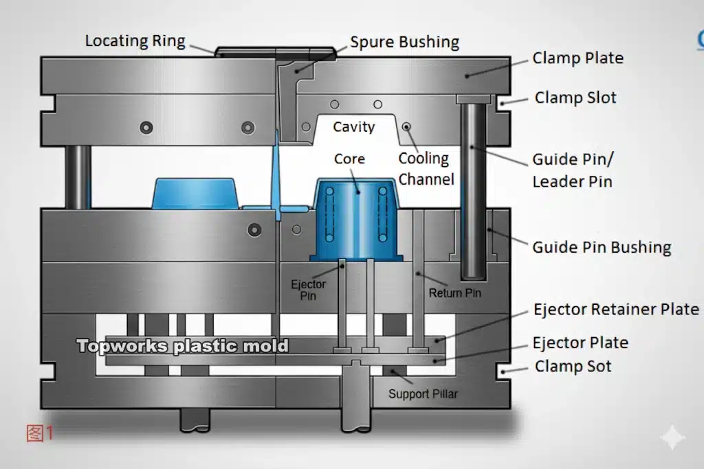
The structure of an injection mold
Injection molds come in all sorts of structures, from 2-plater to hot runner molds depending on application and design requirements, but most typically consist of these elements::
- Mold bases Mold bases offer secure and accurate foundations for molds. The mold rests upon this rigid structure typically constructed out of soft steel such as S50C, P20 or, more expensively, 718, 1.2344 steel.
- An important part of a mold is the mold cavity, Mold cavities play an essential part of molding; they determine both shape and size of molded parts. Hardened steel such as 718, 1.2738, NAK 80, 2344 or S136 is commonly used, often precision machined using high speed CNC or mirror EDM for flawlessness and defect-free results.
- An injection mold’s core determines the internal shape and features of its finished part. A mold cavity, the outer portion that defines its external form, usually features more durable material for external shape creation. As another part of its mold half structure, core inserts may also be attached to something called core half which moves into position when closing up and forms its shape as you close down your mold half. As with all injection mold components, cores play an integral part in molding finished parts based on internal dimensions as well as any external features required by final product manufacturers.
- Molten material enters a mold cavity via its sprue and runners. A gating system directs this flow with multiple gates such as side gates, pin point gates, direct gates, submarrine gates and channels; runners act as passageways from sprue to mold cavity via gates.
- Molten material enters a mold cavity via its sprue and runners. A gating system directs this flow with multiple gates such as side gates, pin point gates, direct gates, submarrine gates and channels; runners act as passageways from sprue to mold cavity via gates. Plastic melt is injected through gates into an injection mold to start flowing outward, and its size and shape has an immediate impact on its final quality. Mold gates typically reside at the surface of mold cavities to evenly disburse molten plastic before molding begins; several varieties will likely be employed depending on material, size and shape requirements of part being produced.
- Cooling systems help material solidify in molded parts while decreasing mold heat production, with cooling time typically accounting for 70 percent of every cycle. Therefore, their presence is absolutely key to effective injection molding processes.
- Ejection systems are used to remove cool and solidified parts from mold cavities. Components in an ejection system include ejector pins, ejection bars, air ejectors, plates and more.
For complex movements or shapes in their parts, injection molds might also include slides or lifters in addition to these core components.

Based on the molding process, the plastic mold is divided into
- injection mold,
- blow mold,
- casting mold,
- pressing mold, and so on.
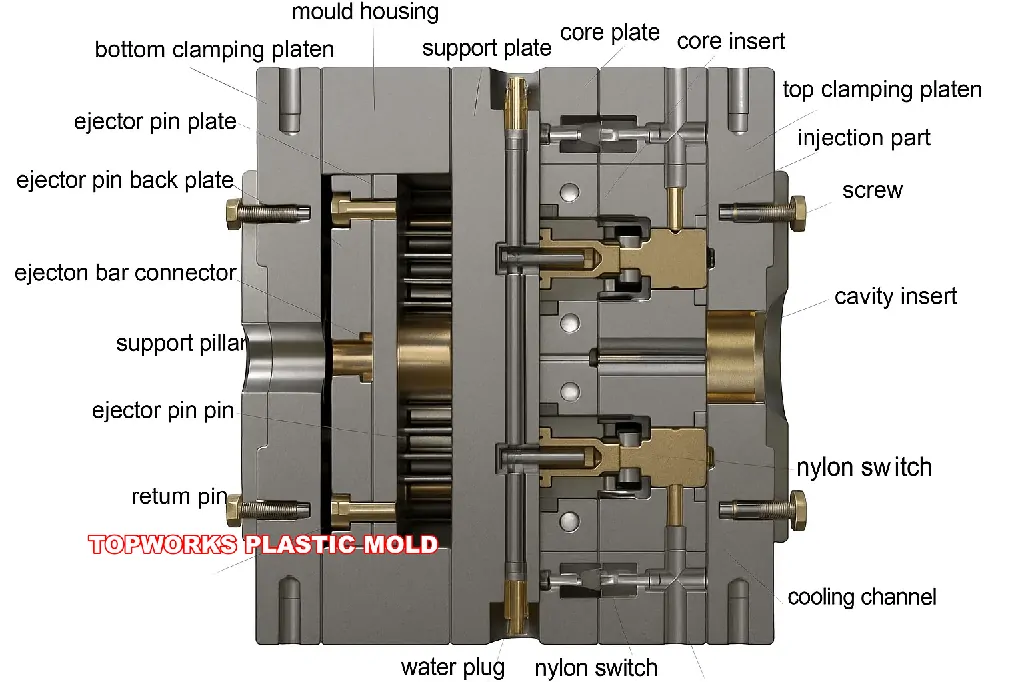
The injection mold comprises two main sections: the moving half and the fixed half.
The moving half is mounted on the moving platen of the injection molding equipment, and the stationary half is mounted on the stationary platen.
Over the injection molding, the moving and the stationary half are shut to develop an injection structure and a cavity structure.
Once the mold is open, the moving half and the stationary half are split up to clear away the plastic item from the plastic mold.
To decrease the mold design and developing period, the majority of the plastic molds work with standard mold bases.
Video Player
00:00
08:06

The injection system and the part forming system are in direct contact with the plastic, and they change with the different plastics and products.Those 2 systems are the most complex and most varied parts in the mold and require the highest finish and accuracy.
The part-forming process refers to the melted plastic heated by an injection molding machine is injected into the mold cavity.After cooling and solidification, it gets the molded products. Which simplifies as mold close – injection – pressure – cooling – mold open – ejection.
Classification of 2 plate and 3 plate injection mold:
| Feature | 2 Plate Mold | 3 Plate Mold |
|---|---|---|
| Alternative Names | Sprue gate mold, Single parting line type | Pinpoint gate mold, Double parting line type |
| Mold Structure | Simple structure | More complex structure (includes extra runner plate) |
| Gate Type | Sprue gate | Pinpoint gate with small cross-section |
| Gate Removal | Manual removal required – sprue is part of the molded part | Automatic removal – no manual removal needed |
| Part Appearance | Standard appearance with visible gate mark | Good appearance with minimal gate mark |
| Automation | Less suitable for automation due to manual gate removal | Advantageous for automation production |
| Cost | Lower cost | Higher cost |
| Applications | Widely used for various kinds of molds | Generally applicable to small and medium plastic parts |
| Material Requirements | Suitable for various materials | Best for plastic molding materials with good fluidity |
| Key Difference | 3 plate mold has an extra runner plate for automatic runner removal | |
The main plastic mold system
There are four key concepts to consider when designing a mold, and the next few lines provide information on how to design a mold.
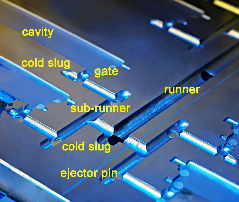
1.Runner
To design a good runner, its geometry, size, and layout also should be correct, in addition to its cooling ability, ejectability, and minimization of regrinds. It is best to fill all cavities at once using a balanced runner system to minimize cycle time and ensure the greatest possible dimensional integrity of the molded product.
The long and thin runners or any runner shaped like a half-moon or a half-circle need to be filled at higher pressures to prevent the mold from cooling down prematurely and causing incomplete parts. The length of a long and thick runner leads to an increase in regrinding, which, in turn, reduces the efficiency of the molding process.
In cases where the runners’ intersections should have ejector pins positioned to eject with sufficient force, ejecting the runner should still be possible. On the ejector portion of the mold, it is preferable to have runners installed to be forced out with the ejector.
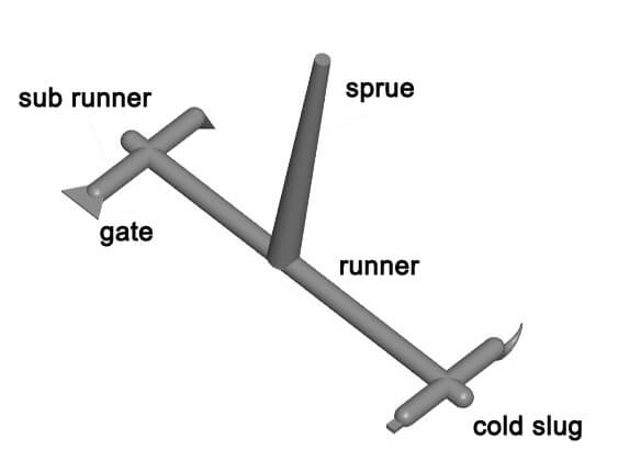
Main Runner
This is a portion of the mold that attaches the nozzle of the injection molding press to the sprue. The top of the sprue is concave for touching with the nozzle.
The one end diameter of the sprue needs to be a little bigger than the nozzle size (0.8 mm) to prevent excessive streaming and avoid the two from being clogged due to wrong positioning.
The size of the one end is determined by the item’s dimensions, generally 4-8 millimeters. The size of the runner ought to be increased inwards at an angle of 3° to 5° to aid the ejection of runners.
In addition to the correct runner geometry, size, and layout, good runners must also be cool quickly, ejectable, and have very little regrind. For filling all cavities simultaneously, a balanced runner system is necessary, which minimizes cycle time and allows the molded product to remain dimensionally intact.
Long and thin runners or half-moon runners require higher injection pressures to ensure that parts aren’t rendered incomplete if the mold cools too quickly. Long and thick runners result in more regrind, which decreases the effectiveness of the operation. Ejector pins should be in place to expel the runners at the convergence of the cold runners.
Runners should be installed at the core half of the mold so that the ejector should be able to push these out of the mold.
Sub-runner
This is basically a small channel joining the primary runner and each cavity for the multi-cavity plastic mold building. As a way to come up with the melted resin occupies the cavity in equivalent velocity, the layout of the runners for the mold needs to be symmetrical and equidistantly spread.
The form and dimension of the runner impact the stream of the plastic melt, the discharge of the item, and the mold building. In many cases, the trapezoidal or semi-circular cross-sections are employed for runner design, and they are machined on ejection half of the mold for the ejector pin to push out.
The exterior of the runner has to be finished to minimize the stream resistance to produce a quicker filling speed. The dimensions of the runner vary according to the sort of plastic material, the dimensions, and the thickness of the item.
For most thermoplastics, the runner’s cross-sectional circumference is not over 8 millimeters, Maximum 10-12 millimeters, Minimum 2-3 millimeters. The cross-sectional region needs to be created as small as possible to decrease the resin misuse and shorten the cooling period.

Cold Slug
It is deemed a prolonged runner situated at the far tip of the main runner to capture the cold resin among the 2 cycles, therefore avoiding the possible blocking of the main runner or the gate.
Should the cold resin blend directly into the cavity, the interior stress will probably stem from the injection-molded item.
The Cold slug features a diameter around 8.5-10.5 mm and 6.5 mm deep. To be able to help ejection, the base is usually grabbed by a puller. The tip of the puller needs to be created to be a zig-zag catch or a depressed slot to ensure that the cold slug might be easily removed in the course of ejection.
2.Temperature Control for cooling
As the injection mold is filled with plastic, it needs to be cooled so that the plastic can solidify and retain its shape. There are various ways to cool an injection mold, and the most effective way depends on the size and shape of the mold.
To meet up the mold temperature demands of the injection molding procedure, a temperature control technology is necessary to regulate the heat level of the mold.
For injection molds to inject thermoplastics, the cooling system is usually built to cool the mold. The most popular way of mold cooling would be to drill cooling water lines inside the mold and work with moving cool liquid to take out the mold’s heat.
Along with heating the mold, hot liquid or vapor should be considered within the water lines, and a heating bar might be mounted within and around the mold.
Mold cooling is an essential metric for determining the quality of the product given to the customer in terms of dimensional integrity, physical properties, surface finish, shrinkage, and the strength of weld lines.
Irregular cooling inside a long cavity will result in poor warpage control. Cooling all core pins is imperative, especially if the ratio of length to the diameter of the core exceeds four. Hot core pins result in surface imperfections and prolong the molding process.
The heat transfer efficiency of a water layer on the pins is much higher than that of the air layer. Ejector pins for flexible resins need cooling before ejection.
The ability to control the temperature of the sprue puller pin area reduces the time it takes to cycle the mold and the number of interruptions it causes during the ejection process.
For effective temperature control, the fluid flow must be high-volume and turbulent.
Prohibiting corrosion within the water lines is achieved by using stainless steel mold plates; other ways to prevent corrosion include plating the cooling channel or adding rust inhibitors into the water. The mold plates must be thick enough to accommodate the cooling channels of proper size.
some facts:
Injection mold cooling systems need to take the location of the cooling lines into account when designing them. Ideally, 12-18mm should be left between the filling and the coolant in the cavity. Coolant lines centers should be approximately 5D apart.
Moreover, cooling lines should not be placed near where the melt flows finally meet, as this can impede plastic flow.
Another factor to consider is the length of the coolant channels. The longer the coolant channel, the more difficult it is to process and the worse the cooling effect. The number of cooling line elbows should not exceed five. The distance between hoses should also not be less than 30mm.
mold width vs diameter of cooling channel
| Mold width | Diameter of cooling channel |
| width < 200mm | 5-6 mm (or 3/16″-1/4″) |
| 200mm<width<400mm | 6-8mm (or 1/4″ – 5/16″) |
| 400mm<width<500mm | 8-10mm (or 5/16″-3/8″) |
| 500mm<width | 10-13mm (or 3/8″-1/2″) |
The type of cooling used for the mold core should also be considered when designing an injection mold cooling system. An insert is the part of the mold that contains the cavities for injecting the plastic.
If the insert diameter is less than 10mm, natural cooling can be used. By using convection, the heat can be dissipated without special cooling lines.
It is possible to use inlaid cooling for cores inserts with a diameter between 10mm and 15mm. By machining channels into the core itself, the core is cooled from the inside.
In order to cool core inserts with diameters between 15 and 25mm, a jet cooling system can be used. A nozzle sprays coolant directly onto the mold core in this system.
A cooling bladder + spacer system can be used for core inserts between 25 mm and 40 mm in diameter. Spacers are used to keep the bladder in place while it is filled with coolant.
The coolant cannot be guided through an injection mold with a large insert diameter (greater than 40mm) and a small height (less than 40mm). Cooling plate systems are better in this situation. The mold core is cooled by a cooling plate placed on top. Coolant flows around the mold core through channels in the plate.
The type of coolant used in an injection mold cooling system is the final consideration. Water is the most common coolant, but there are also oil, air, and CO2 options.
The most effective form of coolant is water, but if it is not properly filtered, it can cause corrosion.
Corrosion does not occur when oil is used in place of water.
The most ineffective coolant is air, but it’s also the safest, since it’s corrosion-free.
However, CO2 is the most expensive type of coolant.
For an injection mold cooling system to be effective and efficient, it is essential to consider all of these factors.
3.Venting
This is a not deep groove cut in the mold to release the air within the cavity or the soft plastic material introduced.
Should the melted resin is shot into the cavity, this kind of trapped air in the cavity needs to be released out of the mold via the grooves at the end of the streaming front in time.
Or else, the item will likely have voids inside(especially for transparent resin injection molding), vulnerable weld lines, um-completed shot -. Perhaps the build-up of air would produce excessive-high temperatures because of the high pressure to make the item charred.

The venting grooves might be situated both at the end of the melt stream and on the P/L of the mold. The last-mentioned place is a shallow slot that is a depth of 0.03-0.2mm and a width of 2-6.5mm cut on the cavity side of the plastic mold.
The vent grooves won’t escape much-smelted resin throughout the shot since the melted resin will cool down around this location and congeal the grooves. The placement of the vent grooves ought not to be confronting the operator to avoid an unexpected splash shot of melted resin. The gap between the ejector pins and the ejector hole, between the ejector bar stripper plate and the core insert, may be a method to release the air.
plastic mold venting slots size:
| Plastic Material | Slot Depth (mm) | Plastic Material | Slot Depth (mm) |
|---|---|---|---|
| PE | 0.02 | ABS | 0.03 |
| PA (GF) | 0.03-0.04 | PC | 0.04 |
| PP | 0.02 | SAN | 0.03 |
| PA | 0.02 | PBT (GF) | 0.03-0.04 |
| PS | 0.02 | ASA | 0.03 |
| PC (GF) | 0.05-0.07 | PBT | 0.02 |
4.Ejection
Ejector pins, sleeves, stripper rings, or stripper plates should work without obstruction to realize consistent ejection.
A guided ejector system allows for precision alignment of the core and pins and will also bear the loads so that the pins do not wear out and go out of alignment. An early return system is another safety feature that should be included.
The early Return system drives all ejector pins into seated positions before the mold closes, ensuring no accidental contact with the ejector that has not fully retracted. Every mold incorporating ejector pins or sleeves under any slides should have a protector pin.
To prevent the ejection pins from colliding with the slides, this lock secures it in the retracted position. Plastic mold should use special ejection systems for parts that consist of flexible, thin-walled, deep sections that are difficult to eject.
How to choose plastic mold steel:
| mold life | <0.2 million | 0.2-0.5 million | 0.5-1 million | > 1 million |
|---|---|---|---|---|
| insert steel | P20/PX5 738 | NAK80/718H | SKD61/TDAC(DH2F) | AIASA420/S136 |
| insert hardness | (30±2)HRC | (38±2)HRC | (52±2)HRC | (60±2)HRC |
| base steel | S55C | S55C | S55C | S55C |
| base hardness | (18±2)HRC | (18±2)HRC | (18±2)HRC | (18±2)HRC |
Mold Development Process

The figure above illustrates and describes an iterative mold development process as is commonly used in mold design, since there are considerably higher levels of interaction between the product design, mold design, and injection molding process.
In order to reduce the time required to develop a product, it is common for the product design and the mold design to be done at the same time. It is true that a product designer can easily estimate the cost of a preliminary part design just by considering the dimensions, thickness, and material of the final part.
In the instance that a mold design could be developed based on this information, a preliminary mold design would be created, and a preliminary quotation would be provided.
Molders will need to design a rough mold for the purpose of doing this preliminary quote. In addition to designing the rough mold, molders will need to estimate critical processing variables such as clamp tonnage, machine hourly rate, and cycle times.
Once the quote has been accepted, the engineering design can begin.
First and foremost, the mold designer will consider many factors before mapping out the design of the mold, such as the type of mold, the number of cavities and their positions, as well as its size and thickness.
Once that is done, each of the subsystems of the mold needs to be designed, which turns out to sometimes mean redesigning subsystems that have already been designed.
In some cases, the cooling system might have to be redesigned, depending on where the ejector(s) are placed.
When the mold design is fully developed, the mold base and other materials can be customized and ordered at the same time to reduce the development time.
The concurrent engineering approach should not be used to design fuzzy aspects of the product. In fact, many mold manufacturers order the mold base and plates upon confirmation of order, so that it arrives in the right time and place.
The lead times typically associated with mold development are now measured in weeks instead of months due to these concurrent engineering practices.
For generations, mold-makers have been creating molds at a faster pace to satisfy the needs of their customers, who have traditionally paid more for faster services.
In the midst of increasing competition, customers are becoming more and more insistent on guarantees regarding mold quality and delivery times, with penalties being applied to missed delivery dates or poor quality levels.
To verify the basic functionality of a mold, molding trials are conducted after the mold has been designed, machined, polished, and assembled.
The moldings will be sampled if no noticeable deficiencies are present, and their quality will be evaluated in relation to specifications. When the mold and molding process are good, they can produce a good product, but they need to be tweaked to increase its quality and to reduce the cost of the product.
There are, however, some instances in which molds contain “fatal flaws” which are not easily repaired and may have to be scrapped and a totally new mold designed.
Elements of a Plastic Mold
Plastic Mold Gates:
The gate of plastic mold refers to a short flow path between the runner and the cavity, which is the entrance of the resin into the cavity.
It is a channel connecting the runner and the cavity.
The cross-sectional area of the gate can be equal to the runner, but it is usually reduced. So it is the smallest part of the entire runner system. The design of the gate is related to the size, shape, mold structure, injection conditions, and properties of the plastic parts.
The role of the gate :
- It could control the flow rate:
- The early solidification of the melt in this part can prevent backward flow:
- The molten material passing through is subjected to strong shearing to increase the temperature; thereby, it will lower the viscosity to increase the fluidity:
- It could facilitate the separation of products and the runner system.

The design of the gate shape, size, and location depend on the plastic, the size, and the structure of the article.The shape of the cross-section of the gate is rectangular or circular, and the cross-sectional area should be small, and the length should be short.
Gate location should generally be selected where the product is thickest without affecting the appearance. The shape, quantity, size, and location of the gate will greatly influence the quality of the plastic parts. So gate selection is one of the key points in plastic mold design.
Direct Gate

- Pros:
1) low-pressure loss;
2) the processing is simple.
- Cons:
1) the stress near the gate is large, and the product stress is uneven and easy to deform.
2) it is necessary to remove the gate with extra works manually. Also, it will leave obvious gate marks on the product surface.
Application:
1) it is suitable for large and deep barrel-shaped parts. For plain parts, it is prone to warpage due to shrinkage and stress.
2) for parts that are not allowed to have gate marks on the surface, the gate can be set into the inner surface of the part, which is an inverted mold.
side gate

- Pros:
1) simple shape and easy machining.
2) it is easier to remove the gate.
- Cons:
1) gate can not separate from the product automatically.
2) the plastic part will leave the gate marks on the plastic part, obviously
Application:
Suitable for all kinds of parts, but not for long barrel profile parts.
pinpoint gate

- Pros:
1)gate position could set on the most surface;
2) the gate can be separated from the part automatically.
3) the gate is small, and the gate marks the glue is small.
4) the stress near the gate location is small, and the injection molded parts are not easy to warp.
- Cons:
1) injection pressure is large, and it is not suitable to use plastic material with poor fluidity.
2) generally use 3 plate mold structure, the mold structure is complex, and the cost is high.
Application:
Because several gate points can be designed, it is often used for shell parts with a larger surface.

- Pros:
1) when the plastic flows through the gate, melt plastic distributes more evenly in the transverse direction and reduces the inner stress.
2) prevent air entry into the cavity and avoid defects, such as silver streaks and bubbles.
- Cons:
1) the part can not be separated from the gate automatically.
2) the remaining gate material will leave on the plastic part and be trimmed manually.
Application:
Commonly used to produce thin sheet and wide parts, and poor fluidity material, such as PC, PMMA, etc.
submarine gate (set on ejector pins or ribs)

- Pros:
1) the choice of gate position is more flexible;
2) the gate can be separated from the plastic part automatically.
3) both the two plate die and the three plate die can be applied.
4) the gate can separate from the plastic part without post-processing of the gate
5) the gate location is inside the plastic parts and will not affect the appearance of the part.
- Cons:
1) the cloudy area is hard to remove.
2) it should cut off the redundant gate relics artificially;
3) the pressure loss from the gate to the cavity is large.
4) the appearance of the plastic part surface may find fingerprinting marks.
5) the machining process is complex;
6) the unreasonable design would easily lead to break the gate and block the gate channel.
Application:
It is suitable for plastic parts with an external appearance with no gate marks allowed.
Commonly used for ABS, HIPS, not used for POM, PBT, and other crystalline materials, also unsuitable for PC, PMMA, and other rigid materials, design should prevent the arc gate from breaking and blocking the gate.
Sliders and lifters
Any structure that hinders the mold opening or ejection is referred to as an undercut. The way to handle the undercut on the mold includes sliders, lifters, core pulling, gear rotating, etc.
The most commonly used is the sliders and the lifters.
sliderThe slider could be set on the static or movement mold plate, and sliders on the movement plate the most widely used.
The slider generally consists of a slide body, locking block(heel), Gibbs, cam pin (angle pin), wear-resistant block, spring, and so on.

- lifter
The lifter generally is used to handle the undercut in the interior of the plastic part. At the same time, the slider generally treats with the external undercut of the plastic parts, but the lifter’s structure is simpler than the slider structure.
The lifter has the function of releasing the internal undercut in the plastic parts, and it can also play the role of ejection.
So the design of the lifter on the mold generally reduces the arrangement of the ejector pins.
The lifter comprises an inclined top body, guide bushing, lifter seat, and wear-resistant block.
Troubleshooting of Plastic Mold Design
To summarize the causes and cures of faults in injection molded components, the Table below should be consulted.

102550100entries per pageSearch:
| PROBLEM | REASON |
|---|---|
| 1. Short shot | The plastic parts made by plastic injection molding companies have irregular and incomplete edges. It usually occurs at the farthest point of the gate, the roots of thin and long ribs. |
| 2, Shrinkage | Occasionally, a place 1. when the material thickness is uneven, 2. thick section of injection molded part, 3. boss and rib section. Due to shrinkage, the plastic parts develop dent, uneven, and wavy under low light |
| 3, Flash | A part edge with an extra thin layer of plastic is often found in the following locations 1. Parting line; 2. Moving core; 3. Ejector pin position, boss position, hole position, snap location |
| 4. Bubbles | The bubbles on the plastic surface are of a different color from the surrounding colors and are typical 1. bubbles caused by gas, air, and water-gas that are not released in time. 2. bubbles caused by shrinkage. The bubbles in the transparent part are particularly distinct. |
| 5. Weld line | When multiple molten flow fronts coincide with each other, a deep weld mark appears on the surface of a plastic part. This most commonly occurs at the confluence of multiple molten flow fronts. |
| 6, Burning | it is not a flat surface. It is usually dark or black spots; usually, they are found in sections where it is difficult to fill and trap the gas easily. |
| 7, Black spots | black impurities are evident on the surface of the plastic parts, mainly caused by the use of mixed materials. |
| 8. Discoloration | The slight difference in color between the actual plastic part and its required color is very apparent, and it is generally because the pigment is incorrect, the mix ratio is incorrect, or the mold is set at the wrong temperature. |
| 9. Wrinkles | The plastic parts show wavy lines on the surface caused by the cooling of the resin flowing. |
| 10. Deformation | The plastic parts have distortions, undulations, curves, and this is particularly common in the bosses, ribs, and round-shaped injection parts. These are especially common to PP injection molding. |
Showing 1 to 10 of 14 entries‹12›

Plasttic Mould Maintenance Handbook
what is plastic mold
Plastic mold is a tool of precision that is used to mold molten plastic into uniform components to be used in mass production. Plastic molds as one of the most important tools of modern production transform complex designs to the repeatable products with strict tolerances and high-quality performance. These tools can be used to produce mass plastic production for automotive interiors, medical disposables and consumer electronics housings.
We are professional mold manufacturers with 18 years experience in mold manufacturing and we are able to combine the choice of steel, cooling design, gating strategy as well as process control to enhance quality, shorter cycle time, and low unit cost. This guide describes plastic mold, plastic types, plastic molding process, plastic materials, plastic industry, plastic cost, plastic quality, plastic problems, plastic trends and plastic tips to select the correct partner and cost saving.
Learning the Basics of Plastic Molds
It is useful to come to an agreement on definitions and structure before settling on a tool. The mechanism and major components of the plastic molding process of the mold have been briefly summarized below.
Definition and Major Components
A plastic mold is a special device that applies injection, blow, compression, transfer, and rotational types of molding to provide thermoplastic or thermoset materials with the final geometry. In the centre lies the cavity (negative of the external shape) and core (creating internal features). Liquid plastic is injected through a system of runners and gates, solidified or heat sunk, and forced out consistently which is a full injection molding cycle. Standard steels are P20, H13 and S136 stainless, and prototypes are made of CNC machining,3d printing and vaccum casting.
Injection molding process: plastic is melted and injected or pressed into the mold cavity under constant pressure and rate from press, and hardens during cooling or curing. The part is ejected after the mold open and the cycle is repeated. The quality of parts is based on material, steel, geometry, gating and cooling layout and process parameters.
| Component | Primary Function | Key Notes |
|---|---|---|
| Cavity | Defines exterior geometry and cosmetic surfaces. | Controls appearance grade; surface finish and texture applied here. |
| Core | Forms internal geometry (bosses, ribs, holes). | Critical for structural features and dimensional stability. |
| Cooling System | Manages cycle time and dimensional stability. | Water lines, baffles, or conformal channels optimize heat removal. |
| Ejection System | Safely releases the part without marks. | Ejector pins, sleeves, lifters, and air valves; timing and placement matter. |
| Runner System | Delivers melt evenly to each cavity. | Includes sprue, runners, and gates; balance flow to avoid defects. |
Related reading: Our Mold Manufacturing Services
Types of Plastic Molds
| Type of Mold | What it is | How it works | Best for | Advantages | Typical Cost | Lead Time |
|---|---|---|---|---|---|---|
| Injection Molds | A mold used on injection molding machines to inject molten plastic into a closed cavity. | Plasticizing → Injection fill → Pack/hold → Cooling → Mold open → Ejection → Repeat. | High-precision functional parts and cosmetic housings (connectors, dashboards, consumer electronics). | High accuracy and repeatability; short cycles at high volumes; supports intricate details. | $5,000–$100,000 | 4–10 weeks |
| Blow Molds | A mold for forming hollow parts. | Parison or preform → Clamp mold → Inflate to conform → Cool → Eject. | Bottles, containers, jerrycans, cosmetic and pharma packaging. | One-step hollow forming; lightweight parts; high material efficiency. | $3,000–$50,000 | 3–8 weeks |
| Compression Molds | A mold for compression forming, often for thermosets or sheet materials. | Place charge → Close and heat/press → Cure → Open and eject. | Large panels, insulators, composite components. | Low shear and internal stress; suited to thick sections and thermosets. | $5,000–$60,000 | 4–10 weeks |
| Transfer Molds | A mold that transfers heated material into cavities—great for parts with inserts. | Preheated charge in a pot → Pressurize → Flow to cavities → Cure → Eject. | Electrical parts with metal inserts, coil bobbins. | Accurate insert positioning; supports fine features and complex geometry. | $8,000–$80,000 | 5–10 weeks |
| Rotational Molds | A mold used in rotomolding for large hollow products. | Load powder → Heat while bi-axially rotating → Uniform coating → Cool → Demold. | Tanks, kayaks, large bins. | Very large seamless hollow parts; uniform wall thickness; low internal stress. | $3,000–$40,000 | 3–8 weeks |
How Does Plastic Molding Work?
Here’s the complete workflow, with injection molding as the anchor example. The same logic applies broadly across other molding methods.
The Complete Process (Step-by-Step)
Step 1: Design Phase(Timeline: 1 weeks)
- CAD design: Part and mold 3D/2D, GD&T, draft, and tolerances.
- DFM analysis: Wall thickness, ribs, radii to reduce warpage and sink.
- Moldflow analysis: Filling balance, weld lines, air traps, cooling, and deflection prediction.
Step 2: Mold Fabrication(Timeline: 2–6 weeks)
- Material selection: P20, H13, S136, or aluminum based on life, resin, and corrosion risk.
- CNC machining: Rough/finish for geometry accuracy; electrodes for EDM.
- EDM machining: Deep pockets, sharp corners, complex details.
- Polishing & texturing: Optical polish (SPI A1/A2) or textures (VDI/MT).
- Assembly: Guides, ejectors, waterlines, hot runner if applicable.
Step 3: Testing & Validation(Timeline: 1–2 weeks)
- T0/T1 trials: Establish process window; evaluate dimensions and cosmetics.
- Inspection: CMM, optical measurement; golden sample definition.
- Optimization: Gate tweaks, venting, cooling balance, steel-safe adjustments.
Step 4: Mass Production
- Stable runs: Repeatable temperatures, pressures, and timing.
- Quality control: FAI, in-process SPC, and final checks.
- Maintenance: Cleaning, lubrication, waterline descaling, and spares management.
Materials Used in Plastic Molds
Selecting the right mold steel and resin pairing drives lifespan, cycle time, and piece price—especially for glass-filled or corrosive materials.
Common Mold Materials
| Material | Properties | Applications | Cost |
|---|---|---|---|
| P20 Steel | Pre-hardened, versatile, economical | Medium-volume molds | $ |
| H13 Steel | High hardness, wear/heat resistant | High-volume, glass-filled resins | $$ |
| S136 Stainless | Corrosion resistant, high polish | Medical, food, transparent parts | $$$ |
| Aluminum | High conductivity, fast machining | Prototypes, short runs | $ |
Plastic Materials for Molding
- ABS: Tough and stable; excellent for cosmetic housings.
- Polypropylene (PP): Light and chemical resistant; packaging and appliances.
- Polyethylene (PE): Tough; common in blow-molded bottles and containers.
- Polycarbonate (PC): Clear and strong; optical and protective parts.
- Nylon (PA): Wear- and heat-resistant; gears and structural components.
Plastic Mold Cost Factors
The most frequent question that we usually get: what is the price of a plastic mold? These are the factors to use to construct an actual budget range.
Factors Affecting Mold Cost
Part Complexity Basic: $2 000-5000 Intermediate: $5 000-20 000 Advanced: $20 000-100 000 and above (e.g., mirror gloss, lifters/slides, micro features)
Mold Size Small less than 500 mm Medium between 500 and 1,000 mm Large more than 1,000 mm (larger tools are more complex to steel, machine and cool)
Volume Requirements Production. 200-1000 shots (prototype); 1000-10,000 (low production); 10,000-100,000 (high production) (hot runners and automation)
Material Selection Tool steel grade; treatments (nitriding, PVD, hard chrome, special needs (SPI optical polish, VDI/MT textures, corrosion control).
Cavity Number Single cavity; Multi-cavity (2-64); Family mold (good flow and shrink control) is necessary.
Tolerance Requirements Standard +-0.1 mm; Precision +-0.02 mm; Ultra-precision +-0.01 mm and environment controlled.
Cost-Saving Tips
- Early design optimization part design (DFM) to eliminate slides, hotspots and sinks.
- Make count of match cavity and ramp match schedule equal to actual requirement.
- Standard components and modular inserts can be used.
- Buy in bulk to cover the cost of tools.
- Cooperation with seasoned manufacturers to reduce trial times.
Mold Cost Calculator
How to decide a plastic mold manufacturer
The appropriate partner establishes lead time, yield and overall cost of ownership. Screen by the criteria below.
Key Criteria to Evaluate:
- Experience & Expertise - Business years, industry specialization (auto/medical/electronics), case tolerances, case depth.
- Quality Certifications- ISO 9001; ISO 13485 (medical); IATF 16949 (automotive).
- Manufacturing Capabilities 5-axis CNC, EDM, CMM; max mold size/tonnage; precision and environmental control.
- Engineering Support- DFM, moldflow, prototyping, hot runner and automation integration.
- Communication/Service - Phase gates, fast after sales support, project management.
The questions to ask about your manufacturer of Mold.
How is your average lead time?
Do you provide DFM analysis?
Which quality control processes do you employ?
Are you able to deal with adjustments and fixes?
What is your warranty policy?
Do you offer tooling storage?
Are you able to offer material certifications?
What are your payment terms?
Quality Control in Mold Manufacturing
Quality is built in with precise measurement, documentation, and adherence to standards.
Inspection Methods
- CMM (Coordinate Measuring Machine)
- Optical measurement and profilometry
- Surface finish testing (Ra, gloss)
- First Article Inspection (FAI), PPAP for automotive
Industry Standards
- ANSI/ASME, DIN, JIS dimensional and tolerance standards
- PPAP and APQP practices for automotive
- Device history records for medical
Common Challenges and Solutions
Most molding issues can be prevented with proactive design and process tuning. Here are frequent problems and fixes.
Warping and Surface Defects in Plastic Molding
| Issue | Problem Description | Causes | Solutions |
|---|---|---|---|
| Warping Issues | Dimensional deformation affecting assembly. | Uneven walls, fiber orientation, unbalanced cooling, residual stress. | Uniform walls and ribbing; balanced cooling; adjust pack/hold and mold temp; select low-shrink or optimized GF content. |
| Flash/Burrs | Excess material along parting line. | Insufficient clamp force, worn parting surfaces, overpacking. | Increase clamp force; refit parting faces; tune injection pressures; gate optimization. |
| Short Shots | Incomplete filling. | Low melt temp, high runner resistance, poor venting. | Raise melt/mold temps; enlarge gate/runner; improve venting; consider higher-flow resin. |
| Sink Marks | Depressions in thick sections. | Localized shrinkage and insufficient packing. | Convert thick walls to ribs; increase pack pressure/time; add local cooling; move or resize gate. |
| Surface Defects | Splay, burn marks, flow lines, visible weld lines. | N/A | Improve drying and venting; reduce shear; apply appropriate texture; reroute flow with gate changes. |
Plastic Mold Technology Trends in the Future
New capabilities are directly translating into reduced cycles, quality, and speedy launches.
- 3D Printing Integration
Allow additive manufacturing Rapid inserts and conformal cooling Rapid inserts and conformal cooling provide faster and evenly cooled parts and extreme cycle time reduction.
- Smart Molds (IoT Sensors)
Data-driven process would reduce the defects, quicker installations, and real-time process windows are embedded with temperature and pressure sensors.
- Sustainable Materials
Improved processable resin recyclable and bio-based with modular cores and replaceable inserts increase space, therefore, extending the life of the tool and waste reduction.
- Design Optimization based on AI
Parameters setting, defects prediction, and automatic gate/cooling with the help of AI reduce trial times, waste, and time-to-market.
Frequently Asked Questions
What is the time it takes to mold a piece of plastic?
How long does a plastic mold last?
Are there plastic molds which can be repaired?
How does a prototype mold differ with a production mold?
What is the best way to keep a plastic mold?
What is the concept of mold flow analysis and why is it so important?
Are you capable of making molds of transparent plastic components?
What is the minimum order quantity?
Do you provide services in design of molds?
What is the price of mold modification?
What are the tolerances possible using injection molds?
Hot or cold runner: Which one is better?
How do I choose mold steel?
What are sink marks, and how to prevent them?
Does it have the ability to run several materials or colors?
How do you protect our IP?
What are the documentation that I get?
Introduction to Your own Plastic Mold Project
You can use this guide to evaluate the plan for production, and it explained the fundamentals: mold architecture, process windows, steels and resin, cost drivers, and quality control.
DFM and moldflow have enabled our engineering team to deliver hundreds of tools to the automotive, medical, and electronics industries, and our team accomplished this by minimizing trial runs and ramp-up time and also due to their ability to achieve tight tolerances and cosmetic quality. Post your 3D files, resin, cosmetic class and volume of the target here,you will receive a transparent, line-item quote and feasibility consultation that will allow to start your business in a flash with confidence.
Ready to Start Your Mold Project?
- ✓ Free DFM Analysis
- ✓ Competitive Pricing
- ✓ Fast Turnaround
- ✓ ISO Certified Quality
Downloadable Resources
- Plastic Mold Steel Selection Guide(pdf)
- Cost Estimation Worksheet (Excel)
- Material Comparison Chart (PDF)
- Mold Maintenance Checklist (PDF)
plastic mold
what is plastic mold
What is Plastic Mold? (Core Definition)
A plastic mold is a precision tool that shapes molten plastic into consistent parts for mass production. As one of the most critical tools in modern manufacturing, plastic molds turn complex designs into repeatable products with tight tolerances and reliable performance. From automotive interiors to medical disposables and consumer electronics housings, these tools enable efficient, scalable output. As professional mold manufacturers with 15+ years of experience, we combine steel selection, cooling design, gating strategy, and process control to improve quality, reduce cycle time, and lower unit cost. In this guide, we explain what is plastic mold, types, the plastic molding process, materials, industries, costs, quality control, challenges, trends, and practical tips to choose the right partner and save budget.
Understanding Plastic Molds – The Basics
Before choosing a tool, it helps to align on definitions and structure. Below is a concise overview of the mold’s mechanism and key components in the plastic molding process.
Definition and Core Components
A plastic mold is a specialized tool used across injection, blow, compression, transfer, and rotational molding to give thermoplastic or thermoset materials their final geometry. At its heart are the cavity (negative of the outer shape) and core (forming internal features). Molten plastic is introduced via a runner and gate system, cooled or heated to solidify, and ejected reliably—cycle after cycle. Typical steels include P20, H13, and S136 stainless, plus aluminum for prototypes, all built with precision alignment, venting, and standardized components to ensure longevity and repeatability.
In practice: plastic is heated to melt, injected or formed into the cavity under controlled pressure and speed, then solidifies during cooling or curing. The mold opens, the part is ejected, and the cycle repeats. Part quality depends on material, steel, geometry, gating and cooling layout, and process parameters.
img alt: "plastic mold structure diagram showing core components"
Key Components of a Plastic Mold
- Cavity – Defines exterior geometry and appearance surfaces.
- Core – Forms internal geometry, bosses, ribs, and holes.
- Cooling System – Water lines, baffles, or conformal channels controlling cycle time and dimensional stability.
- Ejection System – Ejector pins, sleeves, lifters, air valves ensuring safe, mark-free release.
- Runner System – Sprue, runners, and gates delivering melt evenly to each cavity.
Related reading: Our Mold Manufacturing Services · Case Studies/Portfolio
Types of Plastic Molds
Different mold categories fit different shapes, materials, and quantities. Smart selection impacts unit cost, lead time, complexity, and downstream quality.
1) Injection Molds (Most Common)
- What it is: A mold used on injection molding machines to inject molten plastic into a closed cavity.
- How it works: Plasticizing → Injection fill → Pack/hold → Cooling → Mold open → Ejection → Repeat.
- Best for: High-precision functional parts and cosmetic housings (connectors, dashboards, consumer electronics).
Advantages: High accuracy and repeatability; short cycles at high volumes; supports intricate details.
Typical cost: $5,000–$100,000 | Lead time: 4–12 weeks
Example: A multi-cavity automotive switch bezel mold with optimized cooling achieved ±0.02 mm repeatability and 15% shorter cycle time.
2) Blow Molds
- What it is: A mold for forming hollow parts.
- How it works: Parison or preform → Clamp mold → Inflate to conform → Cool → Eject.
- Best for: Bottles, containers, jerrycans, cosmetic and pharma packaging.
Advantages: One-step hollow forming; lightweight parts; high material efficiency.
Typical cost: $3,000–$50,000 | Lead time: 3–8 weeks
3) Compression Molds
- What it is: A mold for compression forming, often for thermosets or sheet materials.
- How it works: Place charge → Close and heat/press → Cure → Open and eject.
- Best for: Large panels, insulators, composite components.
Advantages: Low shear and internal stress; suited to thick sections and thermosets.
Typical cost: $5,000–$60,000 | Lead time: 4–10 weeks
4) Transfer Molds
- What it is: A mold that transfers heated material into cavities—great for parts with inserts.
- How it works: Preheated charge in a pot → Pressurize → Flow to cavities → Cure → Eject.
- Best for: Electrical parts with metal inserts, coil bobbins.
Advantages: Accurate insert positioning; supports fine features and complex geometry.
Typical cost: $8,000–$80,000 | Lead time: 5–12 weeks
5) Rotational Molds
- What it is: A mold used in rotomolding for large hollow products.
- How it works: Load powder → Heat while bi-axially rotating → Uniform coating → Cool → Demold.
- Best for: Tanks, kayaks, large bins.
Advantages: Very large seamless hollow parts; uniform wall thickness; low internal stress.
Typical cost: $3,000–$40,000 | Lead time: 3–8 weeks
| Mold Type | Best For | Cost Range | Production Volume | Complexity |
|---|---|---|---|---|
| Injection | Precision parts | $$$ | High | High |
| Blow | Hollow containers | $$ | High | Medium |
| Compression | Large plates | $$ | Medium–Low | Low |
| Transfer | Insert products | $$$ | Medium | High |
| Rotational | Large tanks | $ | Low | Low |
Learn more: How to Reduce Injection Molding Costs · Our Mold Manufacturing Services
How Does Plastic Molding Work?
Here’s the complete workflow, with injection molding as the anchor example. The same logic applies broadly across other molding methods.
The Complete Process (Step-by-Step)
Step 1: Design Phase(Timeline: 1–2 weeks)
- CAD design: Part and mold 3D/2D, GD&T, draft, and tolerances.
- DFM analysis: Wall thickness, ribs, radii to reduce warpage and sink.
- Moldflow analysis: Filling balance, weld lines, air traps, cooling, and deflection prediction.
Step 2: Mold Fabrication(Timeline: 4–8 weeks)
- Material selection: P20, H13, S136, or aluminum based on life, resin, and corrosion risk.
- CNC machining: Rough/finish for geometry accuracy; electrodes for EDM.
- EDM machining: Deep pockets, sharp corners, complex details.
- Polishing & texturing: Optical polish (SPI A1/A2) or textures (VDI/MT).
- Assembly: Guides, ejectors, waterlines, hot runner if applicable.
Step 3: Testing & Validation(Timeline: 1–2 weeks)
- T0/T1 trials: Establish process window; evaluate dimensions and cosmetics.
- Inspection: CMM, optical measurement; golden sample definition.
- Optimization: Gate tweaks, venting, cooling balance, steel-safe adjustments.
Step 4: Mass Production
- Stable runs: Repeatable temperatures, pressures, and timing.
- Quality control: FAI, in-process SPC, and final checks.
- Maintenance: Cleaning, lubrication, waterline descaling, and spares management.
img alt: "plastic molding workflow diagram with icons"
Explore: Common Injection Molding Defects · Contact/Quote Page
Materials Used in Plastic Molds
Selecting the right mold steel and resin pairing drives lifespan, cycle time, and piece price—especially for glass-filled or corrosive materials.
Common Mold Materials
| Material | Properties | Applications | Cost |
|---|---|---|---|
| P20 Steel | Pre-hardened, versatile, economical | Medium-volume molds | $ |
| H13 Steel | High hardness, wear/heat resistant | High-volume, glass-filled resins | $$ |
| S136 Stainless | Corrosion resistant, high polish | Medical, food, transparent parts | $$$ |
| Aluminum | High conductivity, fast machining | Prototypes, short runs | $ |
Plastic Materials for Molding
- ABS: Tough and stable; excellent for cosmetic housings.
- Polypropylene (PP): Light and chemical resistant; packaging and appliances.
- Polyethylene (PE): Tough; common in blow-molded bottles and containers.
- Polycarbonate (PC): Clear and strong; optical and protective parts.
- Nylon (PA): Wear- and heat-resistant; gears and structural components.
See also: Quality Certifications · Our Mold Manufacturing Services
Industries and Applications
Each industry’s accuracy, compliance, and cosmetic standards influence mold class, steel, and process control strategy.
Automotive Industry
- Interior: dashboards, door panels, trims
- Exterior: bumpers, grilles
- Under-hood: ducts, brackets, fasteners
Case: Multi-cavity interior trim mold with optimized cooling reduced cycle time by 15%, achieved Cpk > 1.67, and scrap < 0.5%.
Browse: Case Studies/Portfolio · Our Mold Manufacturing Services
Medical & Healthcare
- Device housings, disposable consumables, labware
- Compliance: ISO 13485, FDA-related requirements, full traceability
- Tools: S136 stainless with high polish and strict water quality
Learn: Quality Certifications · Contact/Quote Page
Consumer Electronics
- Phone housings, appliance panels, micro-connectors
- Typical precision: ±0.02 mm; high-gloss or textured surfaces
- Hot runners, multi-cavity molds, and robotic handling
Explore: Case Studies/Portfolio · Common Injection Molding Defects
Packaging Industry
- Food containers, cosmetic packaging, caps and closures
- Focus: lightweighting, ultrafast cycles, consistent dimensions
Read next: How to Reduce Injection Molding Costs · Contact/Quote Page
Other Industries
- Toys, building materials, household goods
- Industry note: Automotive represents roughly 30–35% of global plastic mold demand (varies by source).
More: Our Mold Manufacturing Services · Quality Certifications
Plastic Mold Cost Factors
One of the most common questions we receive: how much does a plastic mold cost? Use the factors below to build a realistic budget range.
Factors Affecting Mold Cost
- Part Complexity
Simple: $2,000–$5,000 · Medium: $5,000–$20,000 · High: $20,000–$100,000+ (e.g., mirror gloss, lifters/slides, micro features) - Mold Size
Small < 500 mm · Medium 500–1,000 mm · Large > 1,000 mm (larger tools increase steel, machining, and cooling complexity) - Production Volume Requirements
Prototype 100–1,000 shots; Low 1,000–10,000; High 10,000–1,000,000+ (hot runners and automation for high volumes) - Material Selection
Tool steel grade; treatments (nitriding, PVD, hard chrome); special needs (SPI optical polish, VDI/MT textures, corrosion control) - Cavity Number
Single cavity; Multi-cavity (2–64); Family mold (requires careful flow and shrink balance) - Tolerance Requirements
Standard ±0.1 mm; Precision ±0.02 mm; Ultra-precision ±0.01 mm with environmental control
Cost-Saving Tips
- Optimize part design early (DFM) to reduce slides, hotspots, and sinks.
- Match cavity count to real demand and ramp schedule.
- Use standard components and modular inserts.
- Plan higher volumes to amortize tooling investment.
- Work with experienced manufacturers to cut trial loops.
Share 3D files, target volumes, resin, and cosmetic class for a precise quote.
Get Free QuoteContact EngineerHelpful links: How to Reduce Injection Molding Costs · Contact/Quote Page
How to Choose a Plastic Mold Manufacturer
The right partner determines lead time, yield, and total cost of ownership. Screen by the criteria below.
Key Criteria to Evaluate
- Experience & Expertise – Years in business, domain focus (auto/medical/electronics), proven tolerances and case depth.
- Quality Certifications – ISO 9001; ISO 13485 (medical); IATF 16949 (automotive).
- Manufacturing Capabilities – 5-axis CNC, EDM, CMM; max mold size/tonnage; precision and environment control.
- Engineering Support – DFM, moldflow, prototyping; hot runner and automation integration.
- Communication & Service – Project management, phase gates, fast after-sales support.
Questions to Ask Your Mold Manufacturer
- What is your typical lead time?
- Do you provide DFM analysis?
- What quality control processes do you use?
- Can you handle modifications and repairs?
- What is your warranty policy?
- Do you offer tooling storage?
- Can you provide material certifications?
- What are your payment terms?
See: Our Mold Manufacturing Services · Quality Certifications
Quality Control in Mold Manufacturing
Quality is built in with precise measurement, documentation, and adherence to standards.
Inspection Methods
- CMM (Coordinate Measuring Machine)
- Optical measurement and profilometry
- Surface finish testing (Ra, gloss)
- First Article Inspection (FAI), PPAP for automotive
Industry Standards
- ANSI/ASME, DIN, JIS dimensional and tolerance standards
- PPAP and APQP practices for automotive
- Device history records for medical
Common Challenges and Solutions
Most molding issues can be prevented with proactive design and process tuning. Here are frequent problems and fixes.
Warping Issues
Problem: Dimensional deformation affecting assembly.
Causes: Uneven walls, fiber orientation, unbalanced cooling, residual stress.
Solutions: Uniform walls and ribbing; balanced cooling; adjust pack/hold and mold temp; select low-shrink or optimized GF content.
Flash/Burrs
Problem: Excess material along parting line.
Causes: Insufficient clamp force, worn parting surfaces, overpacking.
Solutions: Increase clamp force; refit parting faces; tune injection pressures; gate optimization.
Short Shots
Problem: Incomplete filling.
Causes: Low melt temp, high runner resistance, poor venting.
Solutions: Raise melt/mold temps; enlarge gate/runner; improve venting; consider higher-flow resin.
Sink Marks
Problem: Depressions in thick sections.
Causes: Localized shrinkage and insufficient packing.
Solutions: Convert thick walls to ribs; increase pack pressure/time; add local cooling; move or resize gate.
Surface Defects
Problem: Splay, burn marks, flow lines, visible weld lines.
Solutions: Improve drying and venting; reduce shear; apply appropriate texture; reroute flow with gate changes.
Deep dive: Common Injection Molding Defects · Case Studies/Portfolio
Future Trends in Plastic Mold Technology
Emerging capabilities are translating directly into shorter cycles, better quality, and faster launches.
3D Printing Integration
Rapid inserts and conformal cooling via additive manufacturing deliver faster, more uniform cooling and significant cycle reductions.
Smart Molds (IoT Sensors)
Embedded temperature and pressure sensors enable real-time process windows, faster setups, and fewer defects through data-driven control.
Sustainable Materials
Recyclable and bio-based resins with improved processability, paired with modular cores and replaceable inserts, extend tool life and reduce waste.
AI-Powered Design Optimization
AI-assisted parameter tuning, defect prediction, and automatic gate/cooling strategies cut trial loops, scrap, and time-to-market.
Useful sources: ScienceDirect: Injection Molding
Frequently Asked Questions
How long does it take to make a plastic mold?
Most projects take 6–12 weeks: 1–2 weeks for CAD/DFM/moldflow, 4–8 weeks for machining and assembly, and 1–2 weeks for trials and optimization. Highly complex tools (multi-action slides, hot runners, multi-cavity) can take longer. Parallel engineering—early steel ordering and pre-purchasing standard parts—can shorten timelines by 10–20%.
What is the lifespan of a plastic mold?
Typical lifespan ranges from 100,000 to 1,000,000+ cycles, depending on steel choice (P20/H13/S136), resin abrasiveness (e.g., glass fiber), process settings (clamp and pack), and maintenance practices (cleaning, lubrication, water quality). Preventive maintenance and corrosion control significantly extend life.
Can plastic molds be repaired?
Yes. Typical repairs include parting line refitting, weld-and-polish on cavities, ejector replacement, hot runner service, and waterline descaling. Cost and downtime depend on damage location and cosmetic requirements.
What’s the difference between a prototype mold and a production mold?
Prototype molds often use aluminum or P20 with fewer cavities for quick validation and low volumes. Production molds employ H13 or S136, hot runners, and automation to support high volumes and tight tolerances with longer service life.
How do I maintain a plastic mold?
Clean and rust-protect routinely, lubricate ejection components, descale cooling lines, verify fasteners, and protect polished/textured faces. Track cycles and maintenance logs for preventive care and predictable uptime.
What is mold flow analysis and why is it important?
Moldflow simulates filling, packing, cooling, and warpage to reveal risks—short shots, weld lines, air traps, deflection—before cutting steel. It reduces trial loops, rework, and launch delays.
Can you make molds for transparent plastic parts?
Yes. Use corrosion-resistant steels (e.g., S136), optical polishing (SPI A0/A1), low-shear gating, proper resin drying, and controlled cooling to prevent stress and haze.
What is the minimum order quantity?
Tooling itself has no fixed MOQ, but select cavity count and tool class to match true demand and budget, balancing upfront investment and piece price.
Do you offer mold design services?
We provide full DFM, moldflow, mold design, BOMs, and 2D drawings, plus manufacturability reports and improvement suggestions.
How much does mold modification cost?
Minor changes (holes, chamfers) can be a few hundred to a few thousand USD. Contour changes or new actions can be $2,000–$15,000+ and may impact lead time.
What tolerances can be achieved with injection molds?
Commonly ±0.05–0.10 mm; precision ±0.02 mm; ultra-precision ±0.01 mm with tight environmental control, stable tooling, and robust metrology.
Hot runner vs. cold runner: which should I choose?
Hot runners reduce waste and cycle time for medium–high volumes. Cold runners have lower upfront cost and suit lower volumes or frequent part changes.
How do I choose mold steel?
Base it on volume, resin abrasiveness/corrosion, cosmetic class, and budget. Medical or transparent parts often favor S136/H13 for corrosion resistance and polishability.
What causes sink marks and how can I avoid them?
Thick sections and insufficient packing are typical causes. Use ribs instead of thick walls, increase pack pressure/time, add local cooling, and optimize gate position.
Can a mold run multiple materials or colors?
Yes via changeable inserts/gates or two-shot/bi-material molds (rotary table or core-back). Expect higher complexity, cost, and lead time.
How do you protect our IP?
NDA coverage, controlled drawing access, tool ID and dedicated storage, restricted photography, and production at approved facilities ensure IP protection.
What documentation do I receive?
3D/2D files, steel and heat-treatment certs, trial and inspection reports, spare parts list, and maintenance guidelines to support stable production.
Get Started with Your Plastic Mold Project
If you’re evaluating what is plastic mold, comparing types, or planning production, this guide clarified the essentials: mold architecture, process windows, steels and resins, cost drivers, and quality controls. Our engineering team has delivered hundreds of tools across automotive, medical, and electronics, using DFM and moldflow to reduce trial iterations and accelerate ramp-up while meeting tight tolerances and cosmetic standards. Share your 3D files, resin, cosmetic class, and target volumes for a transparent, line-item quote and feasibility advice that helps you launch faster with confidence.
Ready to Start Your Mold Project?
- ✓ Free DFM Analysis
- ✓ Competitive Pricing
- ✓ Fast Turnaround
- ✓ ISO Certified Quality
Downloadable Resources
- Plastic Mold Selection Guide (PDF)
- Cost Estimation Worksheet (Excel)
- Material Comparison Chart (PDF)
- Mold Maintenance Checklist (PDF)
Quick links: Our Mold Manufacturing Services · Contact/Quote Page
Internal Linking Strategy (Implementation Notes)
- Insert 8–12 internal links across sections: Services, Portfolio, Quality, Contact, and related blog posts.
- Add 2–3 authoritative external links (ISO, AIAG, peer-reviewed resources).
- Use descriptive anchor text (e.g., “Reduce Injection Molding Costs”).
SEO Checklist
On-Page Elements
- Title tag ≤ 60 chars; single H1; clear H2–H3 hierarchy
- Alt text on all images
- Article + FAQ schema
- Mobile responsive; page speed < 3 seconds
Content Quality
- Original content; 1–2% keyword density for “plastic mold” and “what is plastic mold”
- Paragraphs < 150 words; bullets for scannability
- Visuals every ~300 words (diagrams, tables, icons)
Conversion Elements
- CTA buttons every 2–3 screens
- Contact form, live chat, trust badges, testimonials, phone number