The objective of this report is to provide a final technical and economical analysis of the two major injection mold architectures (2-plate and 3-plate) and material delivery systems (cold runner and hot runner). It will break down their inner workings, evaluate their performance along the important parameters, and provide a strategic framework of how to choose the best option depending on the project needs.
The evolution of injection molding technology reflects a strategy shift to overcome manufacturing issues through mechanical sophistication, which is symbolized by the 3-plate mold, to increased thermal and electrical control, which is symbolized by the current hot runner system. The decision on these systems is not simply a matter of personal preference in the field of technology, but a business decision of strategic importance, having far-reaching implications on the cost-per-part, efficiency of production, end part quality, and the general competitiveness in the market. This is in part because a subliminal understanding of these technologies is essential to the work of any professional involved with product design, the development of tools, and mass production.
Part I: Structural Comparison
To master the use of injection molds, it is important to get acquainted with the basic elements of injection molds. This section talk about the two basic structural patterns, 2-plate and 3-plate molds, upon which all injection molding operations are founded. Their functional difference is determined by their architectural difference, the cost, and the appropriateness to various manufacturing contexts.
2-Plate Mold System
The most widely used and the simplest mold in the injection molding industry is the 2-plate mold. It is characterized by its elegant simplicity and has only one parting line with the single mold divided into two main parts, the fixed side (A-side) and the movable side (B-side). Its plain design makes it incredibly powerful, inexpensive to manufacture, and easy to fix compared to any of its more complex counterparts.
Complex Component Analysis
A 2-plate mold performance is determined by various interaction of several systems:
- Mold Base: The housing to which all other parts are fitted. It typically consists of a top clamping plate (to fit the fixed platen of the molding machine), A-plate, B-plate, spacer blocks, and a rear clamping plate (to fit the moving platen of the molding machine).
- Cavity and Core: This is where the heart of the mold is and it forms the plastic part. The cavity is typically machined into the A-plate to form the outer, and generally cosmetic, surface of the part (the show surface). The internal structure is the core that lies on the B-plate. The accuracy of such parts is directly proportional to the final part dimensional accuracy and surface finish because of precision machining of such parts.
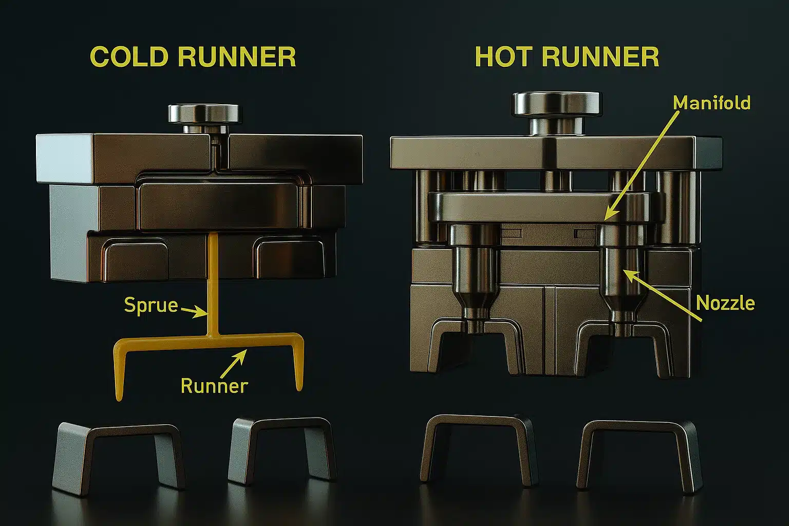
- Cold Runner: This is a system of channels by which the molten plastic is supplied to the cavity. It begins with sprue where the machine nozzle contacts the mold leading to runners, and finally the gates that are the actual points of entry into the cavity. On a typical 2-plate mold, the entire feed system is trimmed on the single parting surface of the A and B plates.
- Ejection System: This system is set in the B-side of the mold and push the solidified part out of the core after the mold opens. Its main parts are ejector pins, which provide the force on the part, ejector guide pins, which straighten the ejector assembly to move correctly, and return pins, which are a critical safety condition that recesses the ejector pins before the mold closing on the next cycle.
- Cooling System: The mold plates are perforated with a system of holes so that they can be cooled with coolant (usually water). This is a mechanism that helps regulate the temperature of the mold such that the molten plastic cools and solidifies rapidly and evenly. Cooling is essential in cutting down the cycle time and preventing defects in the parts like warping or shrinkage.
- Guiding and Alignment System: This will be achieved through the use of guide pins on one plate and matching bushings on the other, which will bring the two halves of the mold into perfect alignment when they close. This precision is highly essential to have a consistent product and prevent tragic losses of the core and cavity.
Operational Principle
A 2-plate mold is easy and predictable. The mold is sealed under high pressure. The machine can then be used to inject molten plastic which flows through the sprue and runner system and into the cavity. The mold is then opened at its single parting line after cooling. As the mold opens, the part and the attached runner system remain on the B-side (core side). Finally, this gets the ejection system into action and the finished piece is pushed off the core with the runner attached to it.
Gating Strategies
Since the runner system is on the parting line, gate positions can only be on the outer edges of the molded part. The most popular gates for 2-plate molds are:
- Sprue Gate: The sprue is often used on the part in single-cavity molds. It is big and creates a huge impression.
- Side Gate: A simple gate set on the side wall of the part.
- Tab Gate: It is a type of side gate but the difference is that the side gate is connected with the part on a small tab which helps in reducing shear stress during filling.
- Fan Gate: A wide and tapering gate for large and flat parts to help with even flow and minimize warpage.
- Submarine (Tunnel) Gate: A very useful type of gate that enters into the section below the parting line at an angle. The gate is automatically sheared off as the part is ejected and does not need degating and can be more automated.
The 2-plate mold is so simple that it is its greatest strength and results in reduced manufacturing costs, shorter build times, and high operational reliability. The same simplicity is limited in its primitive character in some respects, however. Single parting line makes the part and runner eject together (and secondary degating operation is required, unless submarine gates are used) and constrains the location of gates to the outer edges of the part. The result is a direct trade-off; low cost and reliability come at the expense of design flexibility and post-molding labor. This causes the 2-plate cold runner mold to be the most cost-effective and best solution to producing high-volume, simple parts in which the side-gate marks are cosmetically acceptable and the cost of degating is less than the cost of investing in a more complex mold framework. It is the yardstick that all the more advanced systems are measured against.
Mechanical Complexity
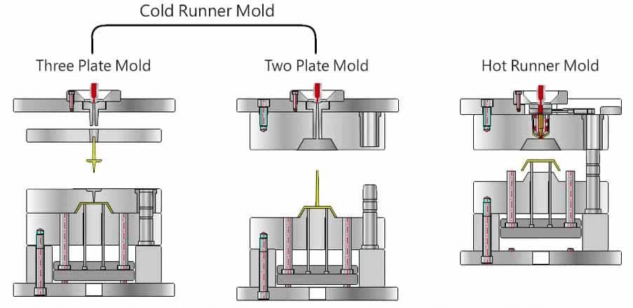
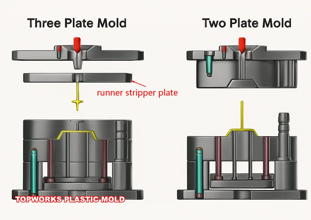
The 3-plate mold is nothing more than a mechanical means of overcoming the natural gating limitations of the 2-plate mold. This is achieved by inserting an extra plate, known as the runner plate, or floating plate, between the rigid top clamping plate and the cavity plate. The plate introduces a second parting line, a feature that is characteristic of the architecture. The runner system can be placed on a different plane and can be ejected separately from the molded part in this design.
Complex Component Analysis
A 3-plate mold is more complicated in its design and constitutes of three major assemblies and special hardware:
- Three Main Assemblies: There are the fixed plate assembly (the sprue bushing and locating ring), the floating runner plate (the runner system), and the moving core plate assembly (the core and the part ejection system).
- Position of Runner System: The sprue feeds to the runner system which is machined on the floating runner plate. This places the material delivery path on a plane parallel, and independent, of the primary parting line where the part is formed.
- Special Hardware: The parting line of the mold has to be opened in a controlled and sequential manner and this implies using more mechanical parts. These are puller bolts, springs, and latching systems that fix the space and timing of every phase of opening. In certain instances, certain runner ejector sets, typically spring-loaded pins, are fitted to actively push the solidified runner off the floating plate during the ejection cycle.
Multi-Stage Opening Sequence
The most pronounced feature of a 3-plate mold is that it has a multi-stage opening sequence, that takes place in three unique stages:
- First Opening (Runner Break/Degating): The molding machine moves the moving part of the mold away. The cavity and runner plates are held together by latches in order to cause the first opening to be between the runner plate and the fixed top plate. This motion cuts the minute pinpoint gates which connect the runner and the part off the surface of the part in a clean-cut fashion. This provides automatic degating.
- Second Opening (Runner Ejection): Opening is continued and the runner plate is ejected by the ejection of the runner plate, using the puller bolts. This forms the second opening or daylight, which gives room to the solidified runner system to be pushed out. The ejector pins are then applied to push the runner off the mold, and it can fall onto a different conveyor.
- Third Opening (Part Ejection): The latching mechanism opens after the second opening and the primary parting line between the cavity and core plates opens. This forms the main daylight and the normal part ejection system moves into force to push the complete and degated part out of the mold.
Sophisticated Gating Capabilities
Probably the greatest advantage of the enormous increase in mechanical complexity is enormous gating flexibility.
- Pinpoint Gates: The architecture supports very small pinpoint gates. These gates may be positioned almost anywhere on the surface of the part including the geometric center since we have the ability to locate the runner on a different plane. That is invaluable in places where the cosmetic appearance is the most important thing and a side gate vestige is unacceptable. There is also a need that large and flat parts or multi-cavity molds should be filled in a balanced fill to prevent the defects on flow.
- Automatic Degating: This is the separation of the part automatically to the runner system through the shearing action of the first opening stage. This obviates the use of a second manual or robotic trimming process, and it saves labor and also leads to greater consistency.
Although the 3-plate mold is effective in automating the degating process and flexibility of gating, the cost is quite high. It is a mechanical brute force solution that introduces a high level of complexity. The third plate and control systems (puller bolts, latches, springs) increase the size, weight, and cost of the mold significantly. That complexity also increases the potential points of failure, and so more maintenance and reputation of being less reliable than a 2-plate mold is also required. In addition, the runner system required by the long and frequently meandering system produces more material waste (scrap) and needs a bigger injection molding machine and a longer opening stroke to handle the numerous parting lines. The 3-plate mold was a significant innovation that made it possible to produce more complex parts throughout the decades but its relevance has been challenged consistently with the introduction of more effective technologies like the hot runners.
Structure: 2-Plate vs. 3-Plate Molds
The two fundamental mold architectures can be directly compared to reveal an apparent trade-off between simplicity and functionality. Selection of them is one of the initial and most significant decisions in the process of tool design.
Structural Complexity
The 2-plate mold is as simple as it gets, having only two main halves and a single parting line, which makes it strong and dependable. The 3-plate mold is also a complex mold in itself, as it adds a third large piece of the mold—the floating runner plate—and the mechanisms involved to drive the multi-stage opening sequence.
Parting Lines
A 2-plate mold has a single parting line. A 3-plate mold is made up of two different parting lines that enable the runner to be separated with the part.
Runner Ejection
Runner solidifies in a 2-plate mold and is ejected with the part. This requires a manual or secondary automated degating unless submarine gates that self-shear are employed. The design of the 3-plate mold allows for the automatic separation of the runner, which is ejected separately in the next step of the mold opening process.
Gating Flexibility
This is the most important difference. The gating of the 2-plate mold can only be on the parting line, so the gates can only be at the outside of the part. The 3-plate mold is infinitely more flexible and allows the use of pinpoint gates, which can be placed at the center or at several locations on the major surface of the part.
Cost and Maintenance
2-plate molds are much cheaper to create, design, and maintain because of their simple construction. 3-plate molds have a higher initial tooling cost, require more intensive maintenance since they are complex, and need larger and more expensive injection molding machines with longer opening strokes.
Cycle Time
2-plate molds tend to have shorter cycle times because of the simpler mechanics and the fact that the runner system is usually smaller and cools quicker. The time-consuming process of opening and closing a 3-plate mold is a natural consequence of its multi-stage process.
Waste of Material
Both are cold runner systems, but the runner system of the 3-plate mold is usually longer and more voluminous to go around the additional plate, which means that more material is wasted with each cycle.
The following table provides a concise, at-a-glance comparison of these two architectures.
Table 1: Head-to-Head Comparison: 2-Plate vs. 3-Plate Mold Architectures
| Feature | 2-Plate Mold | 3-Plate Mold |
|---|---|---|
| Construction | Made up of A and B plates. Long lasting and tough. | More complicated, includes an additional floating runner plate and control hardware. |
| Flexibility of Gating | Very little; gates have to be on the parting line (part periphery). | Allows central or multi-point pinpoint gates on the part surface; it is a high level. |
| Ejection Method | Ejected with the part, and ought to be hand or secondary degated. | The opening of the mold dissociates the part which is ejected automatically. |
| Cycle Time | Faster; less complex mechanicals and cooling. | Longer; because it is difficult to open and close multi-staged. |
| Initial Cost | Cheaper; simpler to plan and build. | More expensive; lots of parts, lots of machining, too big mold base. |
| Maintenance | Less; fewer parts in motion, more points of failure. | More; more complex and hence more upkeep and experience is needed. |
| Waste Material | Reduced amount of runners compared to 3-plate mold. | The runner system is longer, voluminous, and generates more waste. |
| Optimal Applications | Minimum numbers of simple parts that can be permitted to be side gated. | Sensitive areas that are cosmetically gated, centrally gated, or automatically degated areas. |
Cold Vs. Hot Runner Systems
Although the mold architecture determines the physical structure, the runner system determines the way in which molten plastic is conveyed into the structure. This decision on the use of cold and hot runner technology is not related to the number of plates and has a significant influence on manufacturing efficiency, material cost, and final part quality.
The Principles of the Cold Runner System
A cold runner system can be characterized by a series of unheated channels that are machined into the mold plates. It is the standard material delivery technique for both 2-plate molds and 3-plate molds. The name “cold” implies that the runner channels are not heated in an active state, but they cool at the same rate as the rest of the mold assembly.
Process and Relationship between Mold Architecture
Each time there is a cycle of molten plastic released through the machine nozzle, it flows through the sprue, along the runners, and into the cavities. Since the channels are not heated, the plastic in the runner system solidifies at the same time as the plastic that comprises the part. Therefore, the entire solidified plastic material, including the completed parts and the feed system, is removed from the mold at the end of the cycle. The solidified material of the runner can be regarded as scrap, which must be physically removed along with the parts and either disposed of or, where possible, re-ground and sent back into the process.
Cold Runner Systems in Mold Architecture
- 2-Plate Cold Runner: This is the least complicated setup in injection molding. The runner is located on the single parting line and is ejected in an attached state to the parts, requiring a secondary degating operation.
- 3-Plate Cold Runner: The runner system is on a floating plate and is automatically parted off from the parts, ejected separately during the complex opening sequence. Despite its greater mechanical complexity and automatic degating, it remains essentially a cold runner system because the runner solidifies with each injection.
The Pros and Cons
Cold runner systems are still widely used due to several benefits:
- Low Cost and Simplicity: Cold runner molds are much cheaper to manufacture and maintain since they do not involve sophisticated heating components, thermocouples, and temperature controls.
- Material Versatility: They can be used with a wide range of thermoplastics, including thermally sensitive resins that may degrade or burn at melt temperatures in a hot runner manifold.
- Facility of Color Variation: Colors of materials can be changed quickly and easily. The entire feed system solidifies and is ejected with every shot, making it easy to purge the old color with minimal waste during changeovers.
However, these advantages are counterbalanced by serious drawbacks:
- Waste of Material: The solidified runner is waste in itself, significantly raising material costs, especially when using expensive engineering-grade plastics. In industries like medical device manufacturing, regrind is not allowed, making the runner material 100% scrap.
- Increased Cycle Times: Total cycle time is often dictated by the cooling time of the thickest part of the runner system, which can slow down production flow and increase unit costs.
- Secondary Operations: In 2-plate systems, the runner must be physically removed from the parts, introducing additional labor, time, and processes into manufacturing.
- Process Limitations: Molten plastic passes through long, unheated channels, causing cooling and a significant pressure drop, which restricts maximum flow length and complicates filling large or complex multi-cavity tools reproducibly.
Guidelines of the Hot Runner System
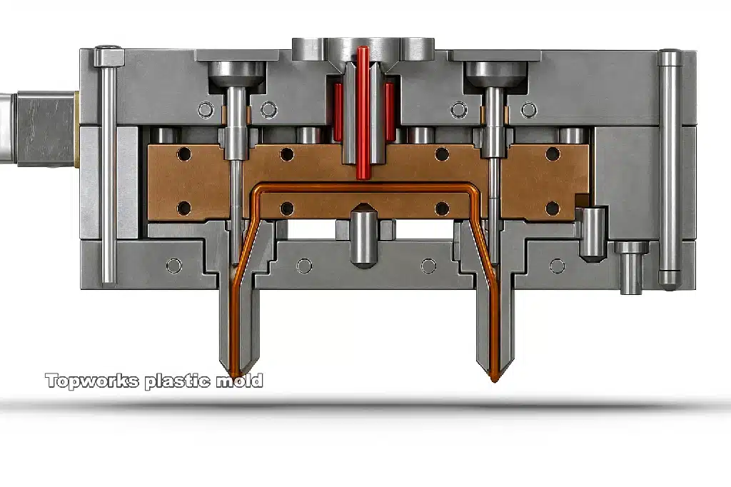
A hot runner system is an advanced setup of heated components, such as a manifold and nozzles, directly installed into an injection mold. It keeps the plastic in a completely molten state between the nozzle of the injection molding machine and the gate of the cavity of the part, effectively removing the solidified runner altogether.
Expanded Parts List
The hot runner system is a sophisticated thermo-electric injection molding system:
- Heated Manifold: The most important part, this is a block of highly machined steel with a network of internal flow channels. Integrated around these channels are heating elements (usually cartridge heaters) that melt the plastic introduced at a central inlet and direct it to a range of nozzles. Advanced manufacturing technologies, such as Plate Fusion Technology, ensure smooth and perfectly round flow paths, reducing shear stress and pressure drop in the material.
- Nozzles (or Drops): These elements carry molten plastic from the manifold into individual part cavities. The nozzles are individually heated, and their temperature is accurately controlled to deliver the plastic at the optimum processing temperature.
- Temperature Controller: An important external component that provides real-time temperature feedback from thermocouples within the manifold and each nozzle. It adjusts the power supplied to heaters to maintain desired temperatures with high precision, typically within a few degrees.
Types of Gates
The gate is the most critical point of contact between the hot runner nozzle and the part cavity. The type of gate used is significant for part cosmetics, quality, and process control. There are two main types:
- Hot Tip (Open Gate): A regular, less expensive option with an open continuous flow channel maintained throughout injection. A small amount of plastic at the end of the cycle melts off, leaving a small, raised nub on the part surface, which is acceptable in many applications.
- Valve Gate: A more advanced and costly system featuring a physical pin that is pneumatically, hydraulically, or electrically controlled. This pin opens the gate to permit flow and closes it at a specific time, offering better control of the filling process, avoiding drooling, and leaving a cosmetically perfect surface with minimal gate remnants. This is ideal for high-precision parts, large components requiring sequential filling, and applications with demanding aesthetic requirements.
Benefits and Limitations of Hot Runner Systems
The following are the main reasons why hot runner systems are becoming the new standard for high-performance molding:
Benefits of Hot Runner Systems
- No Material Waste: The most compelling argument is that hot runner systems do not generate any waste material. The runner system remains in a molten state, eliminating runner scrap. This leads to significant material savings, especially with high-cost engineering polymers or when 100% virgin resin is involved, resulting in a quick payback on the investment.
- Reduced Cycle Times: Since the part is much thicker than the runner, the molding cycle is primarily controlled by the cooling of the part. This decoupling of cooling times is minimal, leading to increased productivity and reduced costs per part.
- Improved Part Quality and Consistency: Direct injection of molten plastic into the cavity under stable pressure and temperature conditions reduces stress and flow-related defects. This results in fewer sink marks, weld lines, and better dimensional stability and uniformity between parts.
- Increased Design Versatility: Hot runner systems provide greater design freedom, allowing for larger parts, thinner walls, and complex multi-cavity tools that would be difficult or impossible to fill using cold runner systems.
Limitations of Hot Runner Systems
Despite their advantages, the introduction of hot runner technology comes with certain disadvantages:
- High Initial Investment: Hot runner systems require a significant capital investment. The costs associated with the manifold, nozzles, and advanced temperature controllers result in a higher initial price for hot runner molds compared to similar cold runner molds.
- More Maintenance Need: These systems are complex and contain numerous components (heaters, thermocouples, valve pins, seals) that may wear out. Maintenance and troubleshooting can be technical and costly, often leading to higher downtime compared to simpler cold runner molds.
- Challenges with Material and Color Switching: Switching between different materials or colors can be time-consuming, as it requires cleaning the internal channels of the manifold and nozzles, leading to material waste. Hot runners are not ideal for projects with constant changes in materials or colors.
- Limitations with Certain Materials: While most polymers can be used, some highly heat-sensitive materials may break down due to extended residence time at melt temperatures in the manifold, potentially altering their properties or causing discoloration.
How to choose?
Choosing between a cold runner system and a hot runner system involves a strategic decision regarding short-term capital investment (CapEx) versus long-term operating costs (OpEx).
Cold Runner System
The cold runner system offers savings during the startup stage, as it allows for the selection of a cheaper, simpler mold. However, it incurs multiplied recurring OpEx due to material waste, longer machine times, and secondary energy expenses.
Hot Runner System
In contrast, the hot runner system requires a higher initial CapEx for advanced molds and controllers but results in lower long-term OpEx by reducing material waste and cycle times while automating the process.
Financial Considerations
This decision is not only technical but also fundamentally financial. A cold runner system may be suitable for a startup, prototype project, or small batch production, providing flexibility and lower initial costs. Conversely, a hot runner system is typically preferred in high-volume manufacturing processes. The efficiency gains and material savings realized per part quickly offset the increased initial costs, leading to greater profitability over the tool’s lifetime.
The robust growth rates of the international hot runner market indicate a general industry trend towards prioritizing long-term operational efficiency over immediate cost savings.
The following table synthesizes the performance characteristics of both systems to aid in this strategic decision.
Table 2: Comprehensive Performance Matrix: Cold Runner vs. Hot Runner Systems
Hot Runner System vs. Cold Runner System
| Feature | Cold Runner System | Hot Runner System |
|---|---|---|
| CapEx (Initial Investment) | Low. The mold shape is simpler, and there are no heaters and controls. | High. Requires an expensive manifold, nozzles, and a complex temperature controller. |
| Per Part Cost (OpEx) | Increased. Motivated by materials, time, and secondary labor expenses wastage. | Lower. Guided by the removal of material waste and much greater production efficiency. |
| Cycle Time | Faster but limited by the cooling time of the thickest part of runners. | Faster. The only limitation is the cooling time of the part, leading to very high productivity gains. |
| Waste Materials | High. The whole solidified runner system is scrap or needs regrinding on every cycle. | Nothing or very little. The runner is melted down and not thrown out, rather than getting rid of scrap. |
| Good Quality | Includes pressure drop and bigger gate remnants. | Excellent. Better process control leads to reduced stress, better cosmetics, and better consistency. |
| Gating Options | Only applicable to mold design (e.g., side gates 2-plate). | Highly flexible. Allows pin point, valve, or edge gating to the part. |
| Thermal Sensitivity | Not as true for certain thermally sensitive polymers that may be destroyed when in contact with too much heat. | Suitable for any kind of polymers, even very heat-sensitive ones. |
| Color Changing | Wide. Fast and easy color changing. | After every shot, the system is cleared. |
| Maintenance | Less costly and easy. Less to break, less to fix, but takes more time and costs more | Hard and delayed. Needs a lot of purging of the internal manifold channels |
| Expertise Required | no need | Needs knowledge of the heaters, thermocouples, and controllers. |
Part III: Application-specific Built-in Systems and Scenarios
This section moves from theory to the practical implementation of mold architectures and technologies. The 2-plate mold combined with hot runner system technology represents a significant milestone in the manufacturing industry. A well-organized system selection plan is crucial for the successful execution of these technologies.
The Hot Runner Two-Plate Mold
The hot runner 2-plate mold combines the structural simplicity and durability of a traditional 2-plate mold with the material delivery efficiency of a hot runner system. This design integrates the hot runner manifold and nozzles into the fixed A-side of a typical 2-plate mold base, allowing molten plastic to flow directly to the gates of the part cavities, eliminating the need for a traditional cold runner.
This hybrid system effectively achieves the primary functional objectives of a complex 3-plate mold, such as flexible gating, central gating, and automatic degating, but without the mechanical complexity. As a runnerless process, only finished products are released from the mold, enabling the fastest possible cycle times.
Comparison to 3-Plate Molds
The hot runner 2-plate mold is increasingly recognized as a more technologically advanced alternative to the cold runner 3-plate mold in many applications:
- Complexity: The hot runner system replaces the mechanical complexity of the third plate and associated components with the thermo-electric complexity of heaters, sensors, and controllers. This trade-off is generally viewed positively, as modern control systems are highly reliable.
- Material Waste: The hot runner 2-plate mold completely eliminates the substantial runner scrap typical of 3-plate designs, leading to significant cost savings.
- Cycle Time: Shorter cycle times are achievable since there are no runners to cool. The mold operates with a single opening and closing motion, in contrast to the multi-step process of 3-plate molds.
- Cost: Although the initial tooling costs for hot runner systems are higher due to the complexity of the hot runner components, the total cost of ownership can be lower compared to 3-plate molds because of material savings, increased productivity, and the potential for using smaller, less expensive molding machines.
A System-Selection and Application Framework
There is no one-size-fits-all mold architecture or runner system. Instead, a careful balance of project-specific requirements must be considered. Four main pillars to analyze for decision-making include:
- Part Complexity: Does the part have complex geometry, undercuts, or thin walls? Is the cosmetic appearance critical, necessitating minimal or masked gate remnants?
- Production Volume: Is this a prototype run (hundreds of pieces), a low quantity run (thousands), or high-volume mass production (hundreds of thousands to millions)? Prototyping and low volumes favor the lower upfront costs of cold runner systems, while the investment in hot runner systems is justified by substantial savings per part in high volumes.
- Type and Cost of Material: Is the polymer a low-cost commodity plastic like polypropylene (PP) or a higher-performance, more expensive engineering polymer like PEEK or glass-filled nylon? Does the material degrade easily with heat? The waste-elimination advantage of hot runners is particularly valuable with high-cost materials, whereas heat-sensitive materials may require cold runners.
- Budget: What is the available capital for the initial tooling investment? A tight budget may necessitate a cold runner system, even if a hot runner would be more cost-effective in the long term.
Applications Case Studies
2-Plate Cold Runner System
Sectors: Consumer goods, Packaging, Toys.
Products: Storage containers, household items, bottle caps, disposable cutlery, simple mechanical gears.
Rationale: These products typically feature simple geometries and are produced in large volumes using commodity resins. The cosmetic requirements allow for side gate marks that can be easily concealed. Thus, the 2-plate cold runner mold is the most economically feasible option due to its low cost, high reliability, and simple structure.
Cold Runner 3-Plate System
Applications: Automotive, Electronics, Medical (typically in legacy applications or special material needs).
Products: Interior automotive parts (dashboards, air vents), cell phone housings, and medical device housings where a clean cosmetic finish with a central gate is necessary, but a hot runner system is not feasible.
Rationale: This system is chosen when a central or multiple-point gate is required by design, and automatic degating must be implemented, but the polymer is too heat-sensitive for a hot runner, or the budget cannot accommodate the additional cost of a hot runner system.
Hot Runner System
Applications: Medical, Automotive, Electronics, High-Volume Packaging industries.
Products: Precision medical components (syringes, IV connectors), automotive sensors and connectors, high-quality electronic enclosures, thin-walled food containers, and any small parts produced in high-cavity molds.
Rationale: The hot runner 2-plate mold is the current standard for high-volume, high-precision production. It eliminates material waste, achieves the shortest possible cycle times, and allows for unlimited gating freedom without the mechanical disadvantages and waste of a 3-plate mold. This system is critical for competing in large-scale, quality production of parts.
The following matrix provides a pragmatic tool for guiding the selection process based on key project drivers.
Mold Comparison: 2-Plate Cold Runner, 3-Plate Cold Runner, and 2-Plate Hot Runner
| Feature | 2-Plate Cold Runner | 3-Plate Cold Runner | 2-Plate Hot Runner |
|---|---|---|---|
| Production Quantity | Ideal for high quantities and prototypes. | Medium volume; does not fit well for large or small volumes. | Sells in bulk; not cost-effective when the volume is low. |
| Simplicity | Ideal for simple parts; can only be applied in simple geometries. | May be used on complex shapes; best on difficult pieces. | freedom of design; on high spec surfaces |
| Quality of Surfaces | Can be put into good quality surfaces (clean pinpoint gates). | Capable of being applied on high-end surfaces (clean pin point or valve gates). | Suitable for high-cost resins; costly resins are squandered. |
| Resin Suitability | Not advisable to use in high-cost resins for big scrap from the runners. | same as 2 plate mold | Suitable for medium-budget; low budgets are unsuitable. |
| Tooling Cost | low | Medium | highest |
Part IV: Economic Analysis and Strategic Investment
Justification of technology choice is significant in a good financial analysis. This section compares the cost of each of the systems and the return on investment so that the professionals can make the decisions not only based on the technical soundness but also economically beneficial.
A Detailed Cost of Tooling and Production Analysis
The price of an injection-molded component is connected to two kinds of costs: the mold cost (Capital Expenditure, or CapEx) that is paid once, and the cost of production (Operational Expenditure, or OpEx) that is used continually.
CapEx (Initial Investment) – The Mold Cost
An injection mold, which can run into a few thousand dollars to a less complex prototype tool, to more than one hundred thousand dollars in the case of some complex, high cavitation production molding tool, will vary depending on a number of items. These include:
- Design and Processing Fees: The costs can be 30-45 percent of the total cost, and it includes the engineering effort to design the mold, and the time on the machines that it requires.
- Material Costs: Material costs amount to approximately 15-30 percent of total cost and comprises the steel to make the core/cavity inserts and the mold base, standard parts.
System Comparison:
- 2-Plate Cold Runner: This is the least expensive system because it is simple in design, standard components are used and it does not require as much complex machining.
- Plate Cold Runner: This is costlier to begin with. This is added to the price by the need of larger more complex mold base, manufacture of the additional floating plate, and the inclusion of specially designed mechanical control elements.
- Hot Runner Mold: This is the priciest one to initiate. The cost of the hot runner system alone is very high and can be up to 40-50 percent of the total cost of material of the mold. A single high-quality nozzle can exceed thousands of dollars and the external temperature controller is another capital cost to consider.
Operational Costs (OpEx) – The Per-Part Cost
Once the mold has been built, the cost of any given part will be what it costs to run:
- Material Cost: The most dramatic OpEx differentiator is the material cost. Each cycle of cold runner systems yields solidified runner scrap. That waste can be as much as or even more than the actual part, and can multiply the cost of material per part by a factor of two or more, in case the resin is costly or cannot be reground. With hot runner systems, there is almost no wastage of any material, because the runner does not solidify.
- Cycle Time Cost: The less the cycle time, the more parts it can make in an hour of machine time. This reduces the fixed costs (machine depreciation, energy, factory overhead) each individual part is charged. The much quicker cycles of hot runner systems result in a reduced per-part cost in terms of machine time.
- Labor Cost: 2-plate cold runner systems typically require additional labor to degate parts, sort scrap and manage the regrind. 3-plate systems have a degree of automation with respect to degating parts but still create scrap that requires handling. Hot runner systems are very automated and do not require these manual procedures at all.
- Maintenance Cost: Cold runners are superior also in this regard. They are also simple and thus easy to maintain and have minimal chances of developing complex failures. The integrated heaters and sensors make hot runner systems complex and expensive to maintain and troubleshoot.
The following table breaks down the primary cost drivers for each system.
Table 4: Cost Driver Analysis: Initial Investment vs. Long-Term Operational Costs
| Cost Driver | 2-Plate Cold Runner | 3-Plate Cold Runner | Hot Runner |
| Initial Investment (CapEx) | Low | Medium | High |
| Mold Base Complexity | Low | High | very high |
| Special Components | None | Pullers, Latches | Full Hot Runner System, Controller |
| Design/Machining Time | Low | High | High |
| Operational Cost Drivers (OpEx) | High | Very High | Low |
| Material Waste (Scrap Rate) | High | Very High (large runner) | None |
| Cycle Time Efficiency | Medium | Low (slow sequence) | High (very fast) |
| Secondary Labor | High (manual degating) | Low (automatic degating) | None |
| Maintenance/Downtime Risk | Low | Medium | High |
Return on Investment (ROI) and Strategic Manufacturing Decisions
The decision to invest in a high-cost hot runner system is justified by its return on investment (ROI). The higher initial CapEx is paid back over time by the cumulative OpEx savings on material, cycle time, and labor.
The ROI Calculation
A break-even analysis is the standard method for quantifying this ROI. It calculates the number of parts that must be produced for the total cost of the hot runner option to become equal to the total cost of the cold runner option. Beyond this break-even volume, the hot runner system generates greater profit with every part produced. The simplified formula is:
Break-Even Volume = (HotRunnerMoldCost−ColdRunnerMoldCost) / (ColdRunnerPer−PartCost−HotRunnerPer−PartCost)
For example, a tool offered by Milacron helps perform this analysis to justify the investment across various scenarios.
Market Trends as Proof of ROI
The most powerful evidence for the proven ROI of hot runner technology lies in its market trajectory. The global hot runner market is a multi-billion dollar industry experiencing strong, sustained growth. It was valued at over $2.8 billion in 2018 and is projected to exceed $5.2 billion by 2026, with some forecasts predicting nearly $6 billion by 2032. The U.S. market alone is expected to reach over $686 million by 2030.
Businesses do not make repeated, large-scale investments in a technology unless it delivers a clear and reliable financial return. This consistent market growth is empirical proof that, for an ever-increasing number of applications, the high initial investment is overwhelmingly justified by the long-term gains in efficiency, quality, and profitability. The fact that the automotive sector and valve gate systems are dominant market segments indicates that the highest value is realized in applications demanding precision, quality, and high-volume output. For a manufacturing professional, choosing a hot runner for a high-volume project is not a speculative risk; it is an alignment with a proven, industry-wide best practice for achieving global competitiveness.
Strategic Alignment
Beyond direct costs, the choice of system aligns with broader business strategies:
- Speed to Market: Faster cycle times can be a critical competitive advantage, allowing a company to meet demand more quickly.
- Sustainability: Eliminating tons of plastic scrap by using a hot runner system aligns with corporate environmental, social, and governance (ESG) goals and can be a powerful marketing tool.
- Quality and Precision: For high-stakes markets like medical devices or aerospace, the superior part quality, reduced stress, and dimensional consistency offered by hot runner systems may be a non-negotiable technical requirement, making the investment mandatory.
Conclusion
The selection of an injection mold architecture and runner system is a foundational decision in modern manufacturing, with far-reaching consequences for cost, quality, and efficiency. The analysis reveals a clear technological progression and a set of distinct trade-offs.
- The 2-plate cold runner mold remains the workhorse of the industry for simple applications. It offers unmatched simplicity and the lowest initial investment, making it ideal for cost-sensitive projects with flexible cosmetic requirements. Its primary drawbacks are material waste and the need for secondary degating operations.
- The 3-plate cold runner mold is a clever mechanical solution that provides the gating flexibility and automatic degating needed for more complex parts. However, its mechanical intricacy leads to higher costs, longer cycle times, greater material waste, and increased maintenance. It is a technology that, while historically important, is increasingly being superseded.
- The hot runner system, most often integrated into a robust 2-plate mold, represents the modern standard for high-volume, high-precision manufacturing. It is a thermo-electric solution that trades high initial capital investment for unparalleled long-term operational efficiency. By eliminating material waste, dramatically reducing cycle times, and offering complete design freedom, it delivers the lowest possible per-part cost and the highest quality for mass production.
Ultimately, the choice hinges on a strategic assessment of four key pillars: Production Volume, Part Complexity, Quality Requirements, and Budget. For low-volume, simple parts on a tight budget, the 2-plate cold runner is the logical choice. For complex parts where a hot runner is not viable due to material or budget constraints, the 3-plate mold remains a potential option. However, for any project aiming for high-volume, high-efficiency, and high-quality output, the evidence overwhelmingly supports the investment in a hot runner system. By carefully analyzing these four pillars in the context of a specific project, manufacturing professionals can confidently navigate the technological trade-offs and select the system that best aligns with both their technical requirements and their strategic business objectives.
ROI and Decisions
The ROI of hot runner systems is worth the huge investment cost of investing in it. The increased initial CapEx is used to offset it down the road with the cumulative savings in OpEx of materials, cycle time, and labor.
Break-Even Analysis
The best-known way to measure this ROI is the break-even analysis. It calculates how many parts will have to be manufactured to make the overall cost of the hot runner system the same as the overall cost of the cold runner system. Any portion made beyond this break-even quantity will earn the hot runner system more money. The abridged form is:
Break-Even Volume = (HotRunnerMoldCost / ColdRunnerMoldCost) * (ColdRunnerPerPartCost / HotRunnerPerPartCost)
ROI in Market Trends
As an example, a tool provided by Milacron assists in carrying out this analysis to justify the investment in different scenarios. It is projected to have a market of over 686 million in the U.S. alone by 2030.
The strongest argument to prove the ROI of the hot runner technology is its market trend. The world hot runner market is a multi-billion dollar business that is showing high sustained growth. It is estimated to have been worth more than 2.8 billion dollars in 2018 and is expected to surpass 5.2 billion dollars by 2026, with some estimating it to reach almost 6 billion dollars by 2032. Businesses will only spend a lot of money and continuously on a technology that gives them a tangible and definite economic reward.
Speed to Market
The faster the cycle times, the more critical it may be as a competitive advantage, enabling a company to respond to demand faster. The steady market growth is empirical evidence that, in more applications, the high initial investment is far outweighed by the long-term efficiency, quality, and profitability benefits. The leading position of the automotive industry and valve gate systems on the market signifies that maximum value is achieved when precision, quality, and high-volume production are required. A manufacturing professional would not take a chance in selecting a hot runner on a high-volume project; it is best practice in manufacturing globally to ensure competitiveness.
Strategic Alignment
In addition to direct costs, there is also a more strategic reason behind the selection of the system:
- Sustainability: Avoiding the tons of plastic waste in the scrap yard with a hot runner system follows corporate environmental, social, and governance (ESG) strategies and can be used in sales and marketing.
- Quality and Precision: The high quality of the parts, lower stress, and dimensional stability achieved by hot runners might be a technical requirement that cannot be sacrificed in high-risk applications like medical devices or aerospace, thus justifying the investment.
The choice of architecture of injection mold and the system of runners is one of the fundamental design choices in modern production, with long-term implications in terms of cost, quality, and efficiency.
Conclusion
It is seen in the analysis that the technological transition is clear and there is a trade-off set. The primary drawbacks are wastage of materials and the secondary degating processes.
The 2-plate cold runner mold continues to be the workhorse in the industry with simple applications. It is the simplest and the least initial cost, making it suited to projects that are cost-sensitive, where the cosmetic requirements are not rigid. The 3-plate cold runner mold is an ingenious mechanical design that offers the flexibility of gating and automatic ejection requirements of more complicated components.
Hot runner systems are the more typical high-volume and high-precision manufacturing systems most often incorporated in heavy-duty 2-plate molds. However, their mechanical complexity makes them more expensive, slows down the cycle time, wastes more material, and costs more to maintain. It is a technology being replaced by others with historical significance.
It is a thermo-electric system that constitutes upscale initial capital investment with excellent long-term operational performance. The 2-plate cold runner makes sense with low budget, simple, and low-volume parts. It has the advantages of never wasting materials, having exponentially reduced cycle times, and providing total design freedom, which results in the lowest cost per part and the best quality in mass production.
Ultimately, the decision will be made based on a strategic analysis of four pillars: Production Volume, Part Complexity, Quality Requirements, and Budget. The 3-plate mold is also applicable in situations of complex components where using a hot runner is not an option due to material or budget constraints. When manufacturing professionals critically evaluate these four pillars in the context of a particular project, they will be positioned to make informed choices regarding technological trade-offs and arrive at the system that best fits their needs in both technical and business strategies. In any project intending to achieve high volume, high efficiency, and high-quality production, there is ample evidence that investing in a hot runner system is well worth the investment.
