
Case Studies
Case Study 1: Side Wall Deformation Control #
Measured correction to eliminate assembly risk before mass production.

Measured side wall deformation created assembly/tolerance risk.

Deformation reduced and verified within the target tolerance window.
Issue #
Side wall deformation caused fitment and tolerance risk during assembly.
Root Cause #
Differential shrink + stress release after ejection, amplified by geometry and cooling imbalance.
Fix #
Measured deformation → tooling correction (support/slider/core) + refined packing/cooling window.
Case Study 2: Flash Defect Elimination #
Structural reinforcement + sealing verification to permanently eliminate flash.
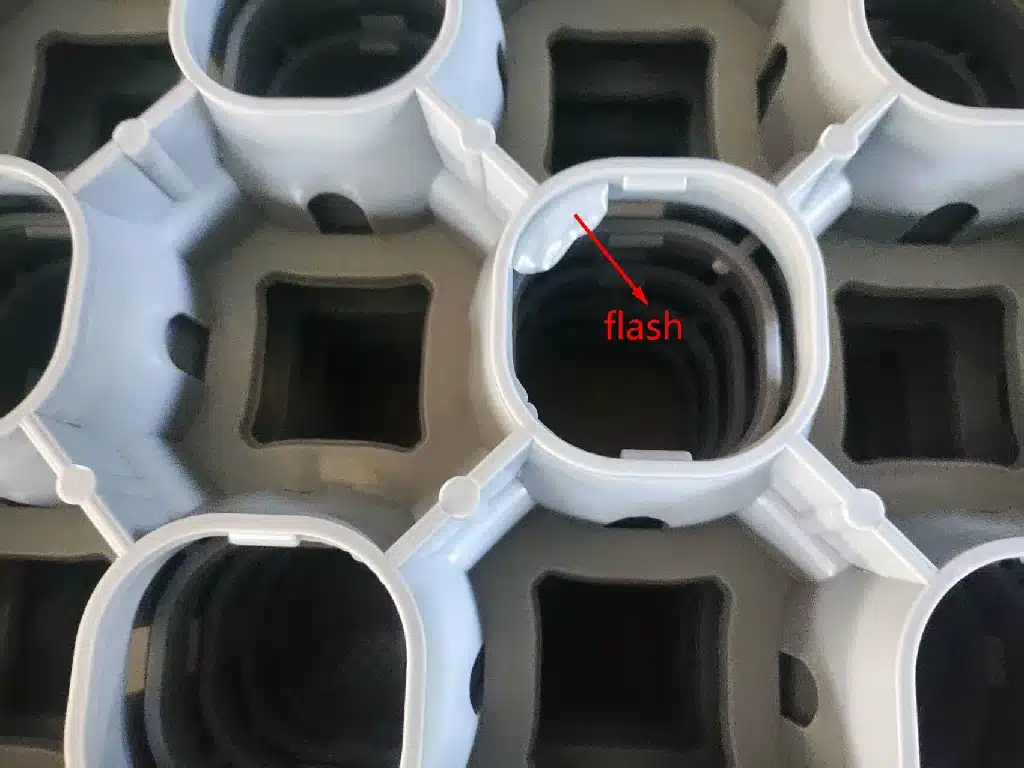
Flash observed along parting line during sampling.
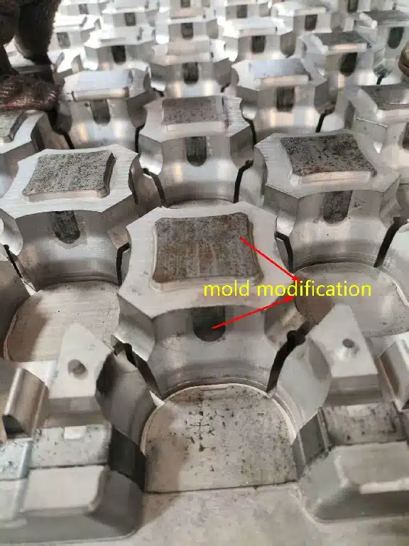
Large mold deflection risk due to insufficient internal support.
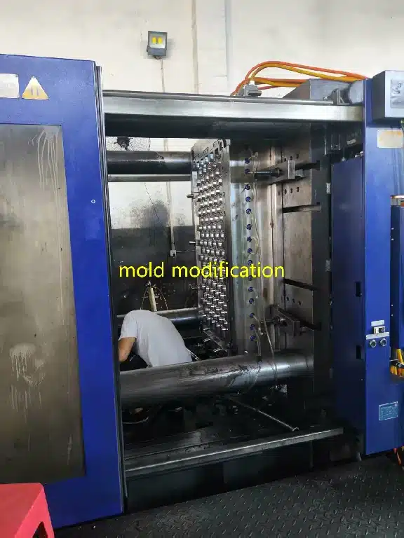
Added pillars + parting line verification to restore sealing.
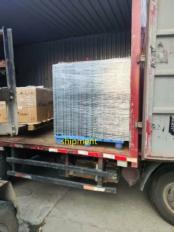
Flash eliminated; production approved and shipped.
Issue #
Flash increased trimming/scrap and created sharp edge & cosmetic risk.
Root Cause #
Large mold deflection under injection pressure due to insufficient support pillars.
Fix #
Added support pillars + verified parting-line contact to restore sealing under pressure.
Case Study 3: Internal Bubble Elimination (Thick-Wall Transparent PC) #
Process tuning + fan-gate freeze-time verification to eliminate internal voids in a transparent PC thick-wall area.

Thick-wall transparent PC section. Differential cooling risk is high in the thick area.

Internal bubble observed in the thick section (surface may look OK, void is inside).

No internal bubble after thermal + packing optimization (material unchanged).

Before/after verification: internal bubbles eliminated in thick-wall areas.
Issue #
Internal bubbles appeared during sampling in the thick-wall transparent area, creating optical rejection risk.
Root Cause #
Outer skin froze early while the core continued to shrink; packing window was insufficient for the thick section.
Fix #
Increase mold temperature and optimize packing profile using fan-gate freeze-time verification.
Case Study 4: Weld Line Improvement #
Process tuning to minimize weld line visibility where flow fronts converge around obstacles.

Visible weld line on part surface; cosmetic and structural risk.

Weld line reduced after speed and temperature adjustment.
Issue #
Visible weld line on part surface created cosmetic rejection and structural weakness risk.
Root Cause #
Melt splits around an obstacle, travels each side, then two cooled fronts re-converge. Cannot be fully eliminated while the obstacle geometry exists.
Fix #
Reduce injection speed + raise mold temperature, with targeted heating at the convergence zone for greatest improvement.

