
7 Crucial Questions to Ask When Evaluating Design for Manufacturability (DFM)
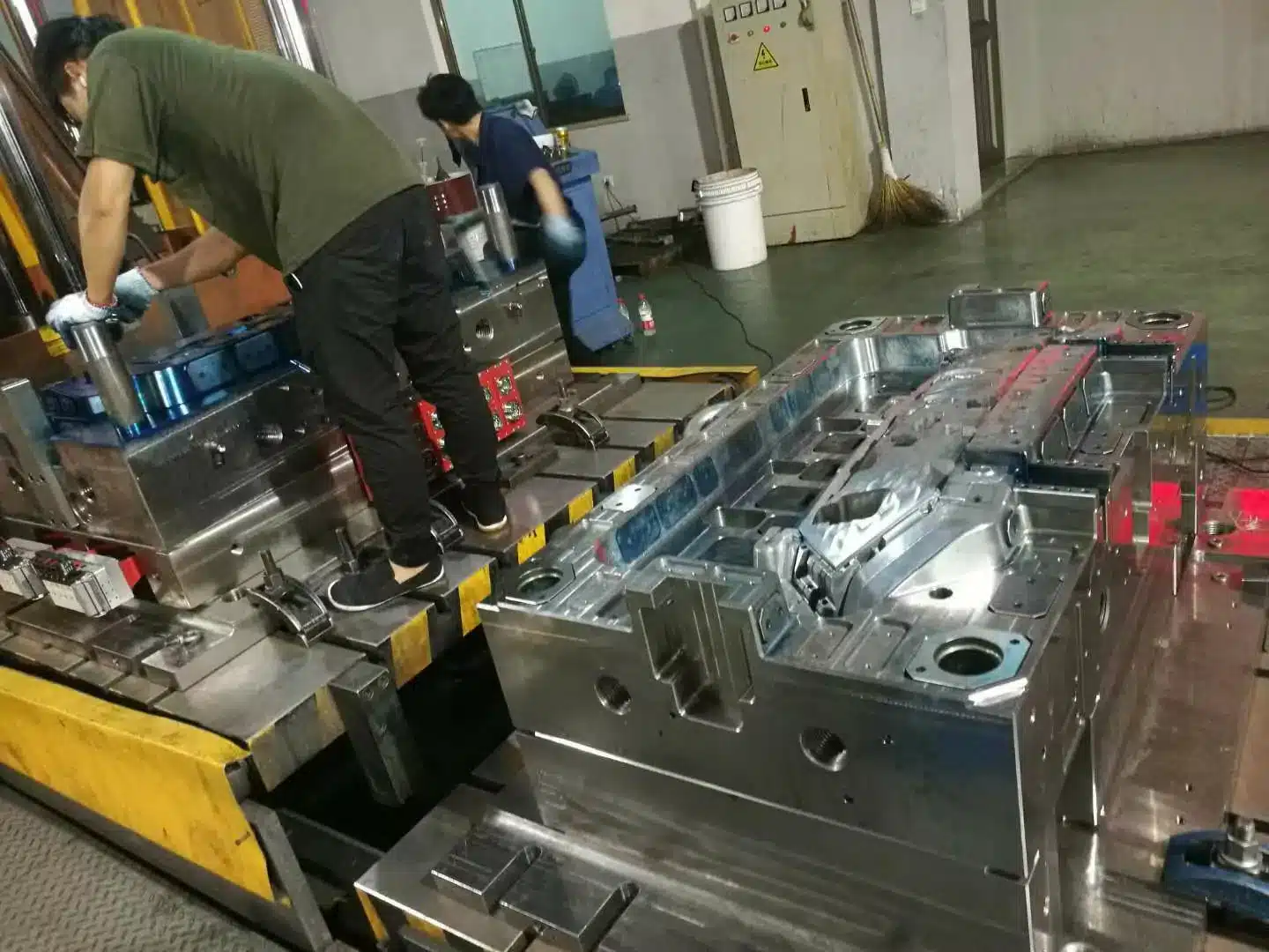
Bringing a new product to market involves much more than just design engineering. To translate innovative ideas into high-quality, cost-effective mass production also requires extensive manufacturing expertise. This is where Design for Manufacturability (DFM) comes in – a pivotal process that helps optimize product designs for efficient, streamlined manufacturing.
Table of Contents
By carefully evaluating DFM early in development, companies can avoid costly mistakes that lead to production inefficiencies down the road. DFM enables engineers to consider manufacturing constraints upfront while designs are still flexible. This allows adjustments to be made easily, reducing rework that causes schedule delays once production is underway. Thorough DFM analysis provides insights to maximize quality, lower cost, and accelerate time-to-market.
This article will explore 7 key questions that engineering and manufacturing teams should ask when assessing DFM for a new product program. Getting the right answers to these questions will help identify areas where design modifications can significantly improve manufacturability. A cross-functional approach to DFM brings unique perspectives to uncover issues that may otherwise go unnoticed. Collaborative DFM analysis between designers, manufacturing engineers, quality engineers, and supply chain specialists enables companies to develop truly optimized designs before committing to tooling.
Design for Injection Molding
Eight checks that decide whether your part molds clean, or fights the tool for its whole life.
Wall thickness rules the whole job
Wall thickness sets cycle time, sink marks, warpage and fill pressure. Cooling time rises with the square of the wall. Double the wall and you roughly quadruple the time the part sits in the tool.
The second rule matters just as much: keep the wall uniform. Plastic shrinks as it cools. A thick zone cools last, keeps shrinking after the gate freezes, and pulls the surface in. That is a sink mark. If the skin is stiff enough to resist, the shrinkage tears a void inside instead.
Hold the nominal wall within ±10% across the part. Where a change is unavoidable, keep the step under 25% of the nominal wall and blend it over a length of at least 3× wall. Never step the wall with a square shoulder.
Cooling time is a first-order estimate from the one-dimensional plate solution. It ignores gate freeze-off, hot runner effects and mold cooling layout. Treat it as a comparison tool, not a quote.
Stiffness comes from ribs, not from thicker walls
Bending stiffness scales with height cubed. A rib 3× the wall height adds far more stiffness than doubling the wall, and it costs almost nothing in cycle time. This is the single highest-value move in plastic part design.
The catch is the rib root. Where the rib meets the wall, material mass builds up. That local thick spot cools last and pulls a sink mark onto the show surface directly opposite the rib.
Base thickness 0.5–0.6× wall for amorphous resins, 0.4–0.5× for high-shrink semi-crystallines. Height up to 3× wall. Draft 0.5–1.5° per side. Root radius 0.25–0.5× wall. Spacing at least 2× wall so the steel between ribs still cools.
Three fixes, in order of cost: move the rib off the show face, break the opposite face with a texture or a styling groove, or core out the wall behind the rib so the mass balances. Adding hold pressure only hides small sinks and often adds stress instead.
Draft is what lets the part leave the steel
A molded part shrinks onto the core. Ejector pins then push it off. With no taper, the part drags the full depth of the core and picks up scuff lines, stress whitening or a torn wall. Draft turns that sliding contact into an instant release.
Texture makes it worse. A grained surface is a field of tiny undercuts. Every 0.025 mm of texture depth needs roughly 1.5° of extra draft on top of the base requirement.
0.5° is the practical floor for a polished vertical face. 1–2° is the normal default. 3° suits a light grain, 5° and up a coarse one. Deep ribs and tall cores want at least 0.5° per side even when the drawing says the face is critical. Shut-off faces and sealing surfaces are the exception, and they need a written agreement before steel is cut.
Sharp inside corners are stress risers
A sharp internal corner concentrates stress, blocks flow and creates a local hot spot in the steel. It is also the place parts break first in drop tests. Adding a radius is free at the design stage and expensive after the tool is cut.
The chart below is the classic stress-concentration curve. Below R/T = 0.3 the factor climbs steeply. Above R/T = 0.6 you gain almost nothing, and you start adding mass that sinks.
Outside radius = inside radius + wall thickness. Do that and the material thickness through the corner stays equal to the nominal wall. Use the same inside radius everywhere so the polisher runs one ball cutter, not five.
Bosses: strong enough to hold a screw, thin enough not to sink
A boss is a rib rolled into a tube. Every rib rule still applies, plus two more. The wall of the boss has to stay thin relative to the nominal wall, and the boss must not sit directly against a side wall, or the two masses merge into one thick lump.
Core the boss from the parting line so the wall stays even. Give the core 0.25–0.5° draft, or it will not release. Stand the boss off the side wall by at least one wall thickness and tie it back with a gusset. Keep thread engagement at 2–2.5× the screw diameter, and add a counterbore at the mouth so the screw starts straight and the top of the boss does not split.
Every undercut buys a moving part in the tool
The cheapest mold opens in one direction and the part falls out. Anything that traps the part needs a slide, a lifter, a collapsible core or an unscrewing unit. Each one adds cost, adds cycle time, adds a witness line on the part, and adds something that can fail at 200,000 shots.
Pick the features your part actually needs. The panel adds up what they do to the tool.
Many undercuts disappear with a small change. Add a pass-through hole in the opposite face so a core pin can form the feature on straight pull. Move the parting line onto a styling break. Split one part into two and weld or clip them. Turn a rigid snap into a shallow bump-off that a flexible resin can strip over. Each of these is worth an hour of CAD work before the RFQ.
The gate decides where the weak lines land
Melt enters at the gate and races outward. Where two flow fronts meet, they form a weld line. That line can be 20–60% weaker than the bulk material, and on a glass-filled resin it is worse, because the fibers lie parallel to the line instead of across it.
Click anywhere in the plate to move the gate and watch the fill pattern change. Openings split the flow and put a weld line downstream of every hole.
Click the plate to place the gate.
Choosing a gate type
| Gate | Auto de-gate | Vestige | Best for | Watch out for |
|---|---|---|---|---|
| Edge / side | No | Trimmed nub | Flat parts, most tooling | Manual trim adds labor |
| Submarine (tunnel) | Yes | Pin mark, hidden | Small to medium parts | High shear, not for filled or brittle resins |
| Hot tip / valve gate | Yes | Small dimple or flat | Cosmetic parts, no runner scrap | Highest tool cost, needs controller |
| Direct sprue | No | Large scar | Thick single-cavity parts | Sink under the gate, long cooling |
| Fan | No | Wide trimmed edge | Wide flat panels, low warp | Needs trim fixture |
| Diaphragm | No | Ring on the bore | Round parts needing concentricity | Secondary machining |
Where can a gate vestige be accepted? Which surface is cosmetic, so the weld line must be moved off it? Is the longest flow path within reach for this resin at this wall? Answer those and the filling analysis usually confirms what you already chose.
Shrinkage first, tolerance second
The cavity is cut larger than the part. How much larger depends on the resin, the wall, the hold pressure and the direction of flow. Semi-crystalline resins shrink two to four times more than amorphous ones, and glass fiber makes shrinkage directional.
That is why a tolerance that is routine in aluminum can be impossible in PP. Ask for tight numbers only where the function needs them, and say which datum they are measured from.
Hold pressure and hold time change shrinkage more than any other setting. Mold temperature comes next, then wall thickness. A part measured hot off the press is not the part you get 48 hours later, especially in PA and POM. Set your inspection window and write it on the drawing.
Values shown follow the general shape of the SPI and DIN 16742 guidance for standard and fine tolerance grades. Use them to sanity-check a drawing early. A final capability statement comes from the mold flow study and the first-article report.
Self-check
Eight questions from the sections above. Answers explain themselves as you go.
I. Does the design minimize parts count and simplify assembly?
Using fewer different parts in making something can make it easier to put together, save time and money, and end up better made. We should aim to get rid of the extra complicated stuff, not just think about what the thing needs to do.The goal should be to eliminate unnecessary complexity rather than focus solely on function. Every part added increases material cost, risks quality issues, and requires additional assembly steps.
Designers ought to think about whether they can merge or get rid of certain parts or make them all the same when they’re looking at ways to use fewer parts. This might mean making one part that does many jobs or changing how things are put together to eliminate parts that aren’t needed. If there are less unique parts with easier shapes, it’s simpler and cheaper to make products and there’s a smaller chance of making mistakes during production.
It’s also key to look at how things are put together to try and mix smaller parts into bigger ones. This way you can have different pieces made at the same time rather than putting together a lot of tiny pieces in order. For instance, it’s better to use one big plastic case rather than several small plates and screws to create a case. Using one big part saves on materials, cuts down on work, and you avoid the risk of making mistakes in complex assemblies.
A good DFM review finds parts that are not needed in the design and points out where things are too complex. It keeps designers from making things too complicated and helps ensure that designs don’t have too many special parts that make it more expensive without really adding value. Any chance to make the number of parts as few and simple as possible is a win for making things easier to manufacture.
II. Can parts be multi-functional?
DFM seeks not only to minimize part count but also optimize part functionality. Well-designed components that serve multiple purposes can further boost manufacturability; using this approach maximizes material usage by spreading functionality over fewer unique parts.
At first glance, certain structural components might also serve as heat sinks, shielding or electrical conduits – multifunctional parts may save costs by fulfilling multiple purposes within their design; engineers must however carefully balance any tradeoffs to prevent overloading part functionality at the expense of performance; highly integrated multifunctional designs may reduce manufacturability if too complex.
Consolidating secondary functions without compromising quality or durability should be at the center of all designs, without comprising quality or durability. Multi-functional component designs which enhance manufacturability require close cooperation among mechanical, electrical and manufacturing engineers and often involve cross-disciplinary collaboration among these teams – this cross-disciplinary approach offers opportunities to distribute functionality more optimally amongst fewer parts.
III. Does the design maximize manufacturing yield?
An essential factor of DFM analysis is how well designs match with manufacturing capabilities. Complex designs with tight tolerances often exceed production methods’ capabilities, leading to decreased manufacturing yield and increasing costs due to scrap rates.
Design engineers should carefully analyze tolerance requirements based on functionality to ensure requirements do not become excessively stringent. Tighter tolerances than can be reliably achieved can result in reject rates exceeding production rates as well as bottlenecked manufacturing operations that diminish profit margins while frustrating line operators trying to meet specifications.
DFM analysis may uncover opportunities to adapt designs in order to expand process windows and improve tolerances, leading to higher yields and yield rates. Sometimes alternative manufacturing approaches may allow looser tolerances than originally specified – for instance using self-fixturing features can achieve precision without overly stringent dimensions requirements; design changes that simplify geometries while expanding tolerances are great examples of sound DFM practices.
IV. Are parts and materials standardized, simple and reliable?
Where possible, designs should utilize standard off-the-shelf components over custom proprietary ones to reduce lead times and costs as suppliers can access inventory more directly than when designing unique parts which require creating tooling or processes to manufacture them. This is often an efficient and economical approach.
Parts with simple geometries and minimal features tend to improve manufacturability, as do those featuring intricate integrally machined features that increase manufacturability. Overly intricate designs with complex integrally machined features often translate to slower production processes with higher costs associated with them; DFM seeks to avoid adding complexity purely for styling rather than functional reasons; in these regards simple parts tend to be produced faster with lower defect rates than more complicated parts.
Material selection is another crucial aspect of DFM. Engineers must carefully select materials and technologies that coincide with available manufacturing methods in their company facilities or supply chains, using proven components from previous product generations if possible to simplify sourcing and production ramp-up; unfamiliar material choices requiring custom processes increase delays or quality issues while standard, simple materials form the cornerstones of DFM.
V. Is the design optimized for fabrication and part consolidation opportunities?
DFM analyzes fabrication and processing steps required to produce each component. This may reveal opportunities to optimize features or consolidate parts for greater efficiency. For example, minimizing the total number of discrete operations and tool changes in CNC machining reduces cycle time and cost.
Designers should explore when components with similar geometries and properties can be combined into single parts to reduce unnecessary interfaces and fasteners and to facilitate assembly more smoothly, for instance consolidating multiple screws, washers, plates or fasteners into a molded plastic part featuring integrated snap-fit fasteners.
Adhesives and welding offer viable alternatives to mechanical fasteners when joining parts together, with DFM helping identify the most efficient joining techniques based on material properties and assembly sequence. Optimized designs which streamline fabrication or facilitate part consolidation can significantly enhance manufacturability.
VI. Does the design enable ease of assembly and serviceability?
DFM also emphasizes assemblability – how well parts and subsystems come together in the factory environment. Interfaces must be designed for seamless assembly operations; an evaluation of full assembly sequence highlights opportunities to optimize components to facilitate easy line installations without interferences or delays.
Serviceability should always be part of any product design; components requiring maintenance or repair throughout its lifespan must be easily accessible for maintenance or repairs, whether that involves PCBAs or motors requiring occasional access or not – clear sight lines with space to allow access for tools will enable fast disassembly without full dismantlement; removable panels/doors providing direct access can simplify field repair/maintenance operations.
Erroneous reassembly after servicing is one of the primary sources of product failures in the field, so Design For Manufacturing strives to develop robust assembly features to prevent improper reinstallation of components. By optimizing assemblies and interfaces for both factory and field operations, products require less manual labor while decreasing assembly defects.
VII. Has the design been optimized to facilitate robotic/toolless assembly?
Automated assembly lines are critical in producing large volume products at lower costs and higher quality levels, and DFM analysis helps identify opportunities for part handling and mating suitable for robots. This may involve including self-locating, self-aligning and self-mating features to facilitate automated installation processes.
Designs should incorporate snap-fit and press-fit fastening methods that require no tools for assembly or disassembly, eliminating or minimizing tool requirements in dismantle/reassembly/reassembly processes. By eliminating screws/tool usage for assembly steps and opting instead for adhesive fasteners for toolless designs.
Automated assembly demands components with simple geometries and interfaces; complex robotic end effectors may also require extensive programming for intricate assemblies; simplified components with foolproof assembly features are key enablers of cost-effective yet high-quality automated production.
This overview of 7 Design for Manufacturability questions illustrates the value of collaborative DFM analysis when developing new products. Too often designs are passed from engineering to manufacturing too late in development processes and result in production inefficiencies; by taking an early cross-functional DFM approach companies can minimize extensive rework for an on-time, on-budget market launch.
DFM provides engineers with a structured methodology for evaluating proposed designs from a manufacturing perspective, helping identify design changes which significantly enhance quality, reduce costs, and speed time-to-market. A small upfront investment to fully evaluate DFM yields smoother production ramp-up and higher long-term profitability; failing to prioritize DFM can cause project delays, costly overruns and field reliability issues that erode competitiveness; thus following established DFM principles is necessary in maximizing competitiveness and increasing long-term success.

