
Humanoid robots · AMRs · cobots · robotic vision · AI servers
Injection Molding for Robotics & AI Hardware
Topworks builds injection molds and molds production plastic parts for robotics and AI hardware — from humanoid robot joint housings, gears and gripper components to sensor housings, battery parts, AI-server fan shrouds, GPU retention parts and cooling hardware.
Injection molded parts for robotics and AI hardware
Injection molding is used for a wide range of robotics and AI hardware components, including robot joint housings, actuator covers, gears, gripper fingers, gripper pads, sensor housings, camera and LiDAR enclosures, cable guides, connector bodies, battery components, electronics enclosures, AI-server fan shrouds, air baffles, GPU retention parts and cooling-system brackets.
The right material depends on the part’s mechanical load, temperature, electrical requirements, dimensional tolerance, surface finish and production volume. Common choices include POM, PA66-GF, PBT-GF, PPA, PPS, PC/ABS, TPU, TPE, LSR and flame-retardant engineering compounds.
Short version: If your robotics or AI hardware has a stable plastic component that needs repeatable production, complex geometry, integrated snap-fits or inserts, or a lower unit cost at volume, injection molding is often worth evaluating.
Why robot parts stall at a general molder
Robotics hardware is not consumer plastic. Low volume, tight stack-ups, engineering resins and frequent design revisions make these projects different from ordinary commodity molding.
What we mold for robotics and AI hardware
Below is the practical part range we target. The exact material and molding process depends on geometry, load, temperature, environment and production volume.
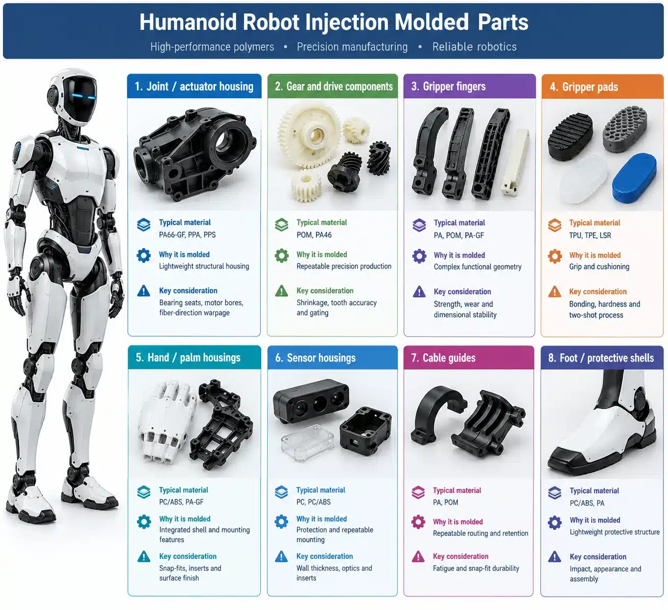
Humanoid robot injection molded parts
| Part | Typical material | Why it is molded | Key consideration |
|---|---|---|---|
| Joint / actuator housing | PA66-GF, PPA, PPS | Lightweight structural housing | Bearing seats, motor bores, fiber-direction warpage |
| Gear and drive components | POM, PA46 | Repeatable precision production | Shrinkage, tooth accuracy and gating |
| Gripper fingers | PA, POM, PA-GF | Complex functional geometry | Strength, wear and dimensional stability |
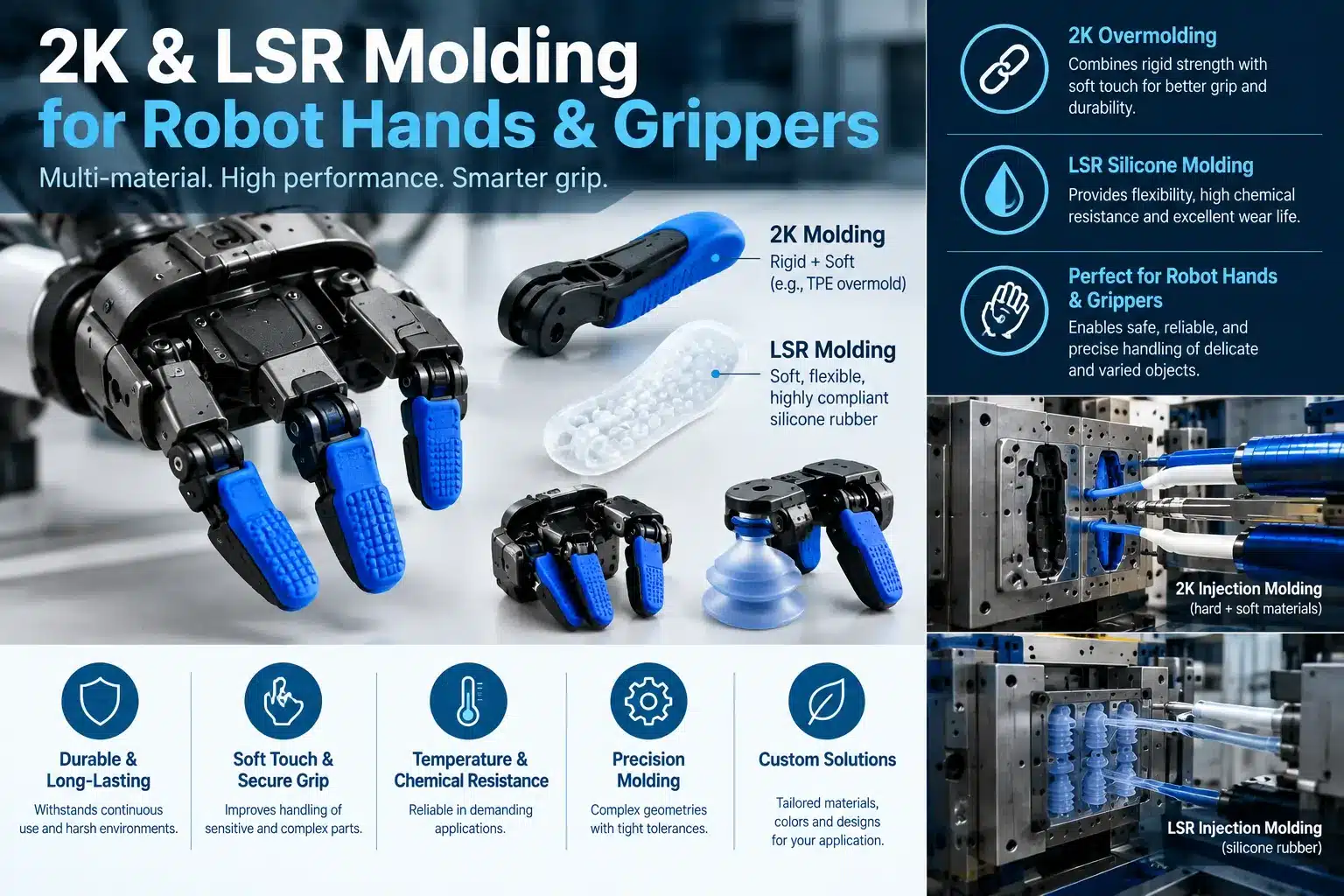
| Gripper pads | TPU, TPE, LSR | Grip and cushioning | Bonding, hardness and two-shot process |
| Hand / palm housings | PC/ABS, PA-GF | Integrated shell and mounting features | Snap-fits, inserts and surface finish |
| Sensor housings | PC, PC/ABS | Protection and repeatable mounting | Wall thickness, optics and inserts |
| Cable guides | PA, POM | Repeatable routing and retention | Fatigue and snap-fit durability |
| Foot / protective shells | PC/ABS, PA | Lightweight protective structure | Impact, appearance and assembly |
AMR, AGV and mobile robot parts
Perception
- LiDAR housings
- Camera housings
- Depth-camera enclosures
- Proximity sensor covers
- Sensor guards
Mechanical
- Wheel covers
- Chassis covers
- Bumpers
- Mounting brackets
- Cable guides
Power & electronics
- Battery covers
- Battery cell holders
- Electronics enclosures
- PCB carriers
- Connector housings
Industrial robots and cobots
Robot arm components
- Joint coversProtect actuator and gearbox assemblies.
- Motor housingsEngineering plastics for lightweight structural components.
- Encoder coversProtect sensing components while maintaining assembly accuracy.
- Cable routing componentsGuides, clips, strain reliefs and harness brackets.
- Tool changer housingsComplex functional geometry with inserts where required.
End-effectors
- Gripper bodiesRigid molded structures for robotic manipulation.
- Gripper fingersPOM, PA or reinforced engineering plastics depending on load.
- Finger padsTPU, TPE or LSR for compliant gripping surfaces.
- Vacuum gripper componentsLightweight molded components for pick-and-place systems.
- Tactile sensor housingsProtection and repeatable positioning of sensing elements.
Robotic vision and sensor components
| Component | Application | Typical material | Important design issue |
|---|---|---|---|
| Camera housing | Machine vision / AI perception | PC, PC/ABS | Optical alignment and inserts |
| Camera bezel | Vision module | ABS, PC | Cosmetic finish and lens clearance |
| LiDAR housing | Autonomous navigation | PC, PC/ABS | Environmental protection and optical openings |
| Depth-camera enclosure | 3D perception | PC/ABS | Dimensional stability around optics |
| Sensor protective cover | Robot perception | PC, TPU | Impact resistance and sensing performance |
Injection molded parts for AI hardware
AI hardware creates another important injection molding opportunity outside the robot itself. Compute systems, edge-AI devices and AI data-center equipment use plastic components for airflow management, electrical isolation, cable management, mounting, protection and cooling assemblies.
AI server and data-center injection molded parts
| Part | Application | Typical material | Key requirement |
|---|---|---|---|
| Fan shroud | AI server cooling | PC-FR, PPS-FR | Flame resistance, heat stability, flatness |
| Air baffle / air duct | GPU and server airflow | PC-FR, ABS-FR | Thin-wall filling and dimensional stability |
| GPU retention rail | AI accelerator mounting | PA-GF, PBT | Strength and dimensional control |
| GPU guide / latch | Card installation | PA-GF, PBT | Wear and repeated service cycles |
| Cable tray / cable clip | Server cable management | PA-GF, PC/ABS | Snap-fit durability and service access |
| PCB carrier | AI electronics | PBT, PC | Electrical insulation and dimensional stability |
| Insulator / standoff | Electrical isolation | PBT, high-CTI compounds | Creepage, clearance and thermal performance |
| Cooling bracket | Liquid or air cooling | PPA, PPS | Temperature and environmental resistance |
Edge AI hardware
Compute and electronics
- AI accelerator enclosures
- Embedded computer housings
- Compute-module covers
- PCB carriers
- Connector housings
- Mounting brackets
Thermal and mechanical
- Fan shrouds
- Air ducts
- Air baffles
- Heat-sink mounting frames
- Cable-management parts
- Protective covers
Robotics and AI injection molding materials
Material selection should start with the function of the component rather than with a generic list of plastics. Load, temperature, friction, electrical performance, flame rating, environment and dimensional stability all affect the choice.
| Material | Typical robotics / AI parts | Main advantage | Molding consideration |
|---|---|---|---|
| POM (acetal) | Gears, cams, bushings, linkages | Low friction and good dimensional stability | Shrinkage and gate position affect precision |
| PA66-GF30 | Arm brackets, joint housings, structural parts | High stiffness and strength at low weight | Fiber orientation can cause directional warpage |
| PC/ABS | Robot shells, covers, electronics enclosures | Impact resistance and cosmetic appearance | Drying and surface control are important |
| PBT-GF | Connectors, cable glands, electrical components | Electrical and thermal performance | Crystallization and thin-wall filling |
| PPA | High-temperature structural and precision components | Dimensional stability and heat resistance | Grade and fiber orientation matter |
| PPS | Actuator parts and high-temperature cooling hardware | High-temperature and chemical resistance | Abrasive to tooling; hardened steel may be required |
| PEEK | High-load precision components | Very high mechanical and thermal performance | High material cost and demanding processing |
| TPU / TPE | Gripper pads, bumpers, seals, strain relief | Flexibility, grip and cushioning | Hardness, bonding and shot design |
| LSR | Robot hand skins, membranes, sealing lips | Elasticity and wide temperature range | Flash control and dedicated LSR tooling |
| PC-FR / PPS-FR | AI-server shrouds, baffles and insulators | Flame resistance and heat stability | Specify the exact grade and required rating |
When should a robotics part be injection molded?
Injection molding is usually worth evaluating when a plastic component has a repeat production requirement and the design is stable enough to justify tooling. It becomes especially attractive when the part has complex geometry, integrated snap-fits, bosses, ribs, inserts or repeated features that would be expensive to machine individually.
| Situation | Often worth considering | Alternative to evaluate |
|---|---|---|
| Prototype / one-off | Prototype tooling if more samples are required | 3D printing or CNC |
| Low-volume pilot | Bridge or prototype injection mold | CNC / additive manufacturing |
| Stable production part | Production injection mold | CNC for very low volume |
| Complex plastic geometry | Injection molding | Multi-axis CNC can become expensive |
| Metal-like strength requirement | Engineering plastics such as PA-GF, PPA or PPS | Die casting or machined metal |
Injection molding vs. CNC for robotics parts
| Factor | Injection molding | CNC machining |
|---|---|---|
| Tooling investment | Higher | Low |
| Unit cost at volume | Usually lower | Usually higher |
| Design changes | More difficult after steel is cut | Easy |
| Complex plastic geometry | Excellent | More machining time |
| Production repeatability | Excellent with a controlled process | Excellent with controlled machining |
| Best fit | Repeat production | Prototype and low-volume parts |
Tooling that matches your robotics project stage
| Tool type | Best for | Typical volume | Trade-off |
|---|---|---|---|
| Aluminium bridge tool | Design still moving | Prototype / pilot | Fast and economical, but less suitable for abrasive resins |
| P20 / 718H steel | Pilot and production | Low to medium production | Good balance of cost, life and machining |
| H13 / S136 hardened steel | Abrasive resins and demanding surfaces | High production | Higher tooling cost and longer build |
| Multi-cavity tool | Stable high-volume production | Higher production | Lower unit cost but poor fit for frequent revisions |
| Two-shot / insert tool | Overmolding, grips and molded-in metal features | Production | More tooling complexity but fewer assembly operations |
The revision problem, handled. On prototype tools we can build changing features as removable inserts. When the robot design changes, the affected steel can often be changed without rebuilding the complete mold.
How a robotics injection molding project runs here
- Day 0 — you send CAD and requirements STEP or IGES, material, expected volume, critical dimensions and target date. NDA first if preferred.
- Day 1–2 — DFM report and quote We review wall thickness, draft, gate and ejector positions, parting line, expected shrinkage and warp risk, tooling cost and unit price.
- Week 1 — mold design for your sign-off 2D layout and 3D mold assembly are reviewed before steel is cut.
- Weeks 2–5 — tool build CNC, EDM, wire cutting, fitting and polishing in our own tool room, with progress updates during construction.
- T1 — samples and measurement report Parts are molded and supplied with dimensional information so design and tooling issues can be identified before production.
- Production — pilot batch, then volume The same tool can move from pilot production to larger production runs when the design and process are ready.
Typical prototype tool: T1 samples can be roughly three to four weeks for a straightforward part in a prototype steel tool. Slides, two-shot and LSR tooling can take longer. The committed schedule is stated in the quotation.
What we measure and send with the parts
| Item | What you receive |
|---|---|
| T1 dimensional report | Critical drawing dimensions measured on sampled parts |
| Tolerance capability | General molding tolerances discussed during DFM; tighter dimensions evaluated individually |
| Material traceability | Resin grade, supplier and lot recorded per production run |
| Surface finish | SPI or VDI reference agreed before texturing where applicable |
| Process record | Process parameters documented for repeat production |
| Mold maintenance log | Shot count and service history for stored tools |
Why robotics and AI hardware teams work with us
One party is accountable. We build the mold and run the molding process. When a part is out of tolerance, there is no argument between a separate toolmaker and molder.
Engineering starts before steel. DFM is where we look at material shrinkage, draft, wall thickness, gating, ejector layout, inserts, tolerance risk and future revisions.
Your mold belongs to you. You own the tooling you pay for. We can store it while you continue production with us or crate and ship it when requested.
We will tell you when injection molding is the wrong process. Some components belong in CNC, die casting, sheet metal or another process. A good manufacturing partner should say so before you spend money on the wrong tool.
Where we are the wrong choice
You need a machined prototype in five days. You require molding physically located inside the US or EU for a specific compliance reason. Or the design is still so unstable that tooling makes no economic sense. In those cases, tell us what you need and we will explain the better route.
Send the CAD. Get a real DFM reply.
Upload a STEP file with your material, expected volume and critical dimensions. We review the molding approach, tooling requirements and production considerations before you commit to the mold.
The engineering behind these part ranges sits in our robotics & AI hardware guide series. Resin choice, gear design, and connector tolerance each get a full guide.
Robotics and AI injection molding questions
What parts can be injection molded for humanoid robots?
Common candidates include joint housings, actuator covers, gears, gripper fingers, gripper pads, hand and palm housings, sensor housings, cable guides, battery covers, protective shells and other structural or cosmetic plastic components.
What plastics are commonly used for robot parts?
POM is commonly considered for gears and low-friction components; PA66-GF for structural parts; PBT for electrical components; PPA and PPS for higher-temperature applications; PC/ABS for housings and covers; and TPU, TPE or LSR for compliant gripping, sealing and protective components.
What plastic is suitable for a robot joint housing?
PA66-GF, PPA and PPS can be candidates depending on load, temperature, dimensional requirements and environment. The final selection should be based on the actual part geometry and operating conditions rather than material name alone.
Can robot gears be injection molded?
Yes. POM and selected nylon grades are commonly considered for molded gears. Tooth accuracy depends on material shrinkage, fiber content, gate location, cooling, tooling accuracy and the gear’s operating load.
Can gripper pads be made by two-shot injection molding?
Yes. TPU, TPE or LSR can be molded over a rigid substrate when the material, geometry and bonding system are suitable. This can eliminate a separate adhesive or assembly operation.
Can sensor and camera housings be injection molded?
Yes. PC and PC/ABS are common candidates for protective sensor and camera housings. The mold design must account for optical alignment, wall thickness, inserts, mounting datums and the required surface finish.
What injection molded parts are used in AI servers?
Potential components include fan shrouds, air baffles, air ducts, GPU guides, retention rails, cable-management parts, PCB carriers, insulators, standoffs and cooling brackets.
What plastics are used for AI-server cooling components?
Depending on temperature, flame requirements and chemical environment, candidates can include flame-retardant PC, PPS, PPA and other engineering compounds. The exact grade should be selected against the required thermal and safety specifications.
Can AI hardware cooling components be injection molded?
Yes. Fan shrouds, air baffles, ducts, brackets and selected liquid-cooling components can be candidates for injection molding when the material and operating environment are appropriate.
Can I injection mold a robotics part in a low volume?
Yes. A prototype or bridge tool can make sense when the design needs enough production parts to justify tooling. The best approach depends on expected total volume, material, geometry and how often the design will change.
How long does a robotics injection mold take?
A straightforward prototype steel tool can reach T1 in roughly three to four weeks. Slides, complex mechanisms, two-shot tooling, LSR and demanding surface finishes can require additional time. The project schedule is confirmed during quotation.
Can I revise the mold after the robot design changes?
Yes. Where future changes are expected, removable inserts can be used for selected features. This can make later revisions substantially easier than cutting an entirely new mold.
Can you hold ±0.03 mm on a molded robot component?
Some features can achieve tight tolerances with the right material, geometry, tooling and process control, but ±0.03 mm should not be treated as a universal molding tolerance. Critical features are reviewed individually during DFM, and machining after molding may be recommended where appropriate.
Do you handle insert molding for robotics and AI hardware?
Yes. Metal inserts such as threaded bushings, shafts, contacts and other components can be incorporated into molded parts when the design and production volume justify the process.
Should I use injection molding, CNC or 3D printing for my robot part?
For one-off prototypes, CNC or additive manufacturing can be simpler. Injection molding becomes increasingly attractive when a plastic part needs repeat production, complex molded geometry and lower unit cost at volume. We review the CAD and recommend the appropriate process during DFM.
