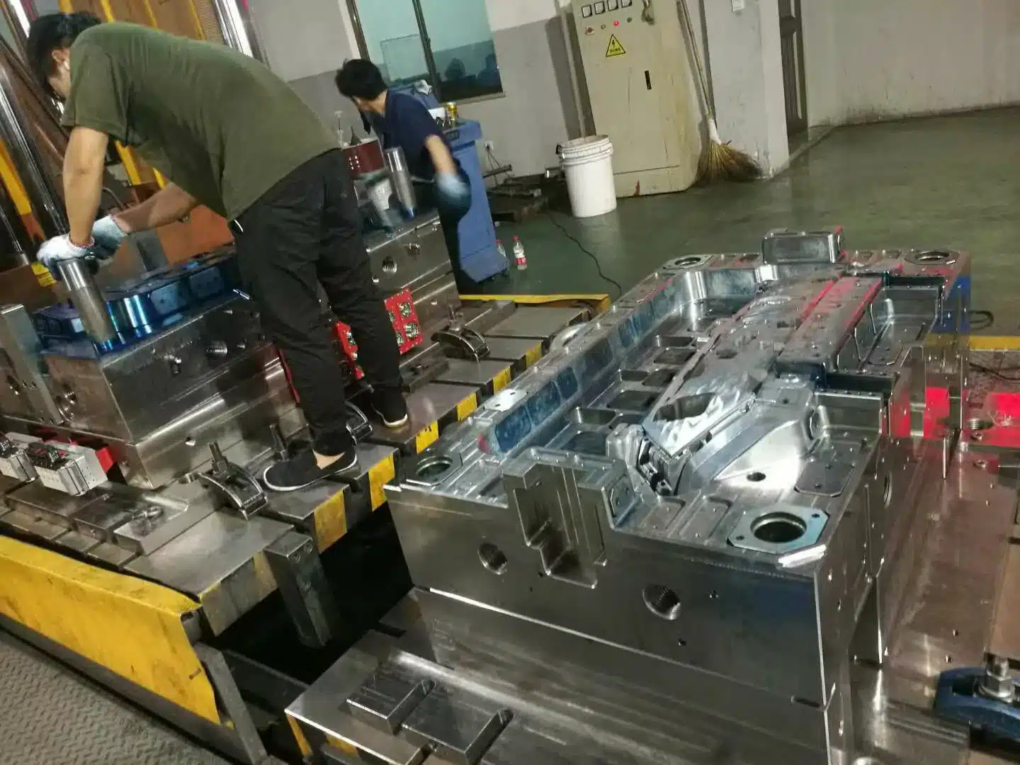

Product Development Workflow
Systematic Design Procedure for Injection Molded Parts
Developing a new injection molded part from initial concept to mass production requires coordinating material selection, tooling design, press equipment sizing, and unit-cost targets. Following a structured 5-stage engineering procedure prevents costly mold rework and accelerates time to market.
- Stage 1 — Problem Definition: Isolate functional load, environmental, and cost constraints before sketching geometry.
- Stage 2 — Trade Literature & Patent Audit: Search technical periodicals and U.S. Patent Office filings to benchmark prior art and avoid infringement.
- Stage 3 — Concept Crystallization: Translate abstract concepts into dimensioned sketches, 3D CAD drawings, and written engineering specifications.
- Stage 4 — Peer DFM Review & Prototyping: Validate assembly clearances, moldability, and patentability through physical functional models.
- Stage 5 — Production Tooling Release: Finalize operation sheets, quality standards, and multi-cavity mold specifications.

The 5-Stage Engineering Procedure
| Development Stage | Core Engineering Deliverable | Commercial & Tooling Impact |
|---|---|---|
| 1. Establish the Problem Area | Written functional & economic boundary specification | Prevents over-engineering and aligns part cost with market targets |
| 2. Collect Facts & Patent Prior Art | Trade literature survey + U.S. Patent Office search | Prevents reinventing existing mechanisms and identifies patentable features |
| 3. Crystallize the Design | Engineering sketches, 3D drawings, and written specs | Converts raw concepts into manufacturable geometries ready for DFM |
| 4. Peer Review & Physical Models | Cross-departmental DFM review + prototype test models | Verifies assembly tolerances, moldability, and patent claims before cutting steel |
| 5. Tooling & Process Standardization | Mold design, operation sheets, and quality standards | Locks in repeatable plastic product manufacturing economics |
1. Define the Engineering Problem Area
Every systematic product development program begins by defining the exact functional and economic problem. An engineer cannot optimize wall thickness, resin grade, or design of tools until mechanical loads, assembly interfaces, and target piece prices are stated clearly. Challenging legacy assumptions—such as consolidating multi-piece metal assemblies into a single molded plastic housing—unlocks the largest cost reductions.

2. Survey Technical Literature and Issued Patents
Once the problem boundaries are set, gather existing engineering data before starting CAD work. Review resin supplier datasheets, trade periodicals, and issued filings from the United States Patent Office. Studying issued patents reveals how previous engineers solved similar mechanical latching, sealing, or molding challenges and highlights opportunities for new patent protection.
3. Crystallize Concepts into Drawings and Specifications
An engineering concept has commercial value only when communicated clearly to toolmakers and management. Crystallize the design as early as possible by recording the geometry in dimensioned sketches, 3D mechanical drawings, and written material specifications.
4. Validate with Cross-Functional Reviews and Physical Models
Review the preliminary drawings with mold designers, press operators, and assembly engineers to catch undercuts or draft issues early. Building physical prototype models and running accelerated life tests proves out both functional durability and patentability before committing capital to hardened production steel.
Ready to turn your part drawings and specifications into production-ready mold tooling? Send your CAD files to our engineering team for a systematic DFM review.

