[language-switcher]
Guide to Briefing Your Designer on a Plastic Part
Big Picture & Priorities
Your goal is to tell the part’s function, environment, manufacturing, appearance, assembly, and cost—in that order. Mark each requirement as Must / Nice-to-have / Can-drop. Getting function boundaries and manufacturing constraints on the table early prevents rework.
Key Information Checklist (fill-in friendly)
If you cover each item below in one crisp sentence, your designer can start right away.
Use case & function
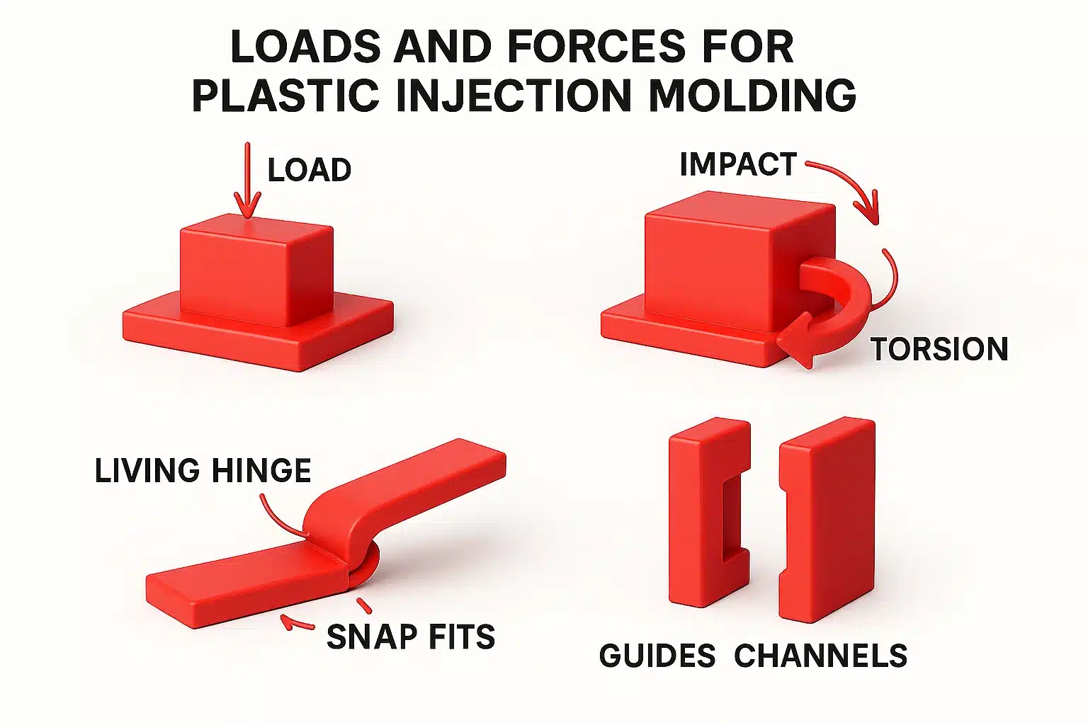
- Loads and forces: How much load? Impact/torsion? Need living hinges, snap fits, guides, channels?
- Life & cycles: Disposable vs repeat use, open/close cycles, fatigue expectations
- Environment: Temperature range, humidity, outdoor/UV, chemicals (alcohol, oil, cleaners)
Envelope & dimensions
- Overall envelope: L × W × H, available space, keep-out/interference zones
- Critical dimensions & tolerances: Which dimensions are “fit-or-fail”? Target tolerance class
- Cosmetic surfaces: Which are A-surfaces (visible)? Surface quality level and texture direction
Assembly & interfaces
- Mating parts: Screws, metal inserts, snap fits, rails, O-rings/seals
- Assembly process: Order of operations, self-locating features, draft/pull direction for snaps
- Serviceability: Need to be removable? Anti-reverse assembly features, poka-yoke
Material & process
- Candidate materials/traits: ABS, PC, PP, PA, TPE… target properties (stiffness, toughness, flame rating, weatherability, food-safe)
- Molding process: Injection molding? Overmold/2K/insert molding? 3D-printed prototypes for validation?
- Wall and reinforcement: Preferred nominal wall, rib locations/height/fillets
- Draft & demolding: Required draft angles, acceptable parting line zones, ejection mark zones
Surface & cosmetics
- Texture/paint/plating/print: Which faces get texture, grade; any paint or plating (impacts snap strength and tolerances)
- Color & color variation: Target color code, acceptable ΔE range
- Cosmetic defects tolerance: Where weld lines, sink, or ejection marks are unacceptable
Reliability & compliance
- Tests: Drop height, crush, IP rating, salt spray, UV
- Certifications/standards: RoHS/REACH, UL94 flammability, food contact, medical grade
Cost & volume
- Volume and takt: Pilot vs mass production, target cycle time
- Target piece price: e.g., “post-mold unit cost ≤ $X”
- Tooling strategy: Cavity count, hot vs cold runner, tool life, shared tools/family tools
Timeline & deliverables
- Milestones: Concept → Feasibility → DFM review → Alpha → Beta → MP
- Risks & unknowns: Structures/materials to validate, how many prototype loops are acceptable
DFM Essentials (make it manufacturable)
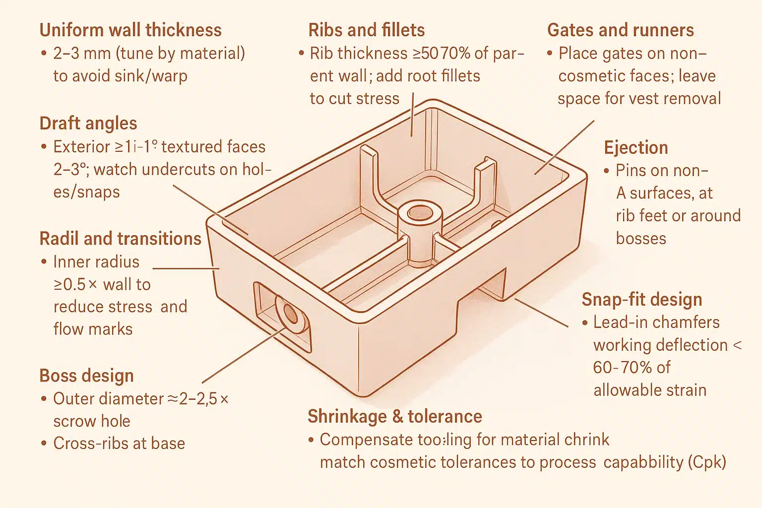
- Uniform wall thickness: Prefer 2–3 mm (tune by material) to avoid sink/warp
- Ribs and fillets: Rib thickness ~50–70% of parent wall; add root fillets to cut stress
- Draft angles: Exterior ≥1°; textured faces 2–3°; watch undercuts on holes/snaps
- Radii and transitions: Inner radius ≥0.5× wall to reduce stress and flow marks
- Gates and runners: Place gates on non-cosmetic faces; leave space for vest removal
- Ejection: Put pins on non-A surfaces, at rib feet or around bosses; add ejector pads
- Boss design: Outer diameter ≈ 2–2.5× screw hole; cross-ribs at base for strength
- Snap-fit design: Lead-in chamfers; working deflection < 60–70% of allowable strain
- Shrinkage & tolerance: Compensate tooling for material shrink; match cosmetic tolerances to process capability (Cpk)
Suggested Drawings and Handoff Package
- 3-view + exploded view: Mark A-surfaces, parting line, gate, ejector zones, draft direction
- KPC drawing: Only the few dimensions that are function-critical with tolerances
- Material and finish list: Grade, color code, texture spec, paint/print process cards
- Assembly guide: Sequence, any jigs/fixtures
- Risk map: Potential sink/weld lines/stress hotspots with fallback options
One-page Requirements Template (copy/paste)
- Project/part name:
- Use case & function (loads/environment):
- Envelope (L × W × H, keep-out zones):
- Critical interfaces & assembly method:
- Material & process (candidates, wall, overmold/insert?):
- Cosmetics (A-surfaces, texture/paint/plating, color code, no-defect zones):
- Dimensions & tolerances (KPC list):
- Reliability & compliance (tests, certifications):
- Volume & cost (annual qty, unit cost target, tooling strategy):
- Timeline (milestones & prototype plan):
- Risks & unknowns (items to validate, Plan B):
Quick Takeaways
- Lead with function and environment, then structure and manufacturing. Tag each requirement Must/Nice/Drop.
- A single-page brief plus a simple sketch gets your designer into DFM mode fast and cuts iterations.
- Call out only a few truly critical dimensions; let design and process absorb the rest for stable mass production.
