Design Principles for Plastic Parts
Introduction: The Significance of Design in Plastic Part Manufacturing
Injection molding allows companies to produce many plastic parts across different industries. The process generates precise shapes by amazing standards. The key challenge in injection molding starts with creating perfect designs from the very beginning. Your design plan determines all the essential aspects of your product including functionality and pricing and production viability.
A well-designed product prevents many potential difficulties from arising. The process produces several manufacturing defects such as sink marks combined with empty gaps as well as bending and cracking. These problems cause both aesthetic damage and strength reduction in the final part. Our team faced project warping issues because we failed to properly plan the design. What a headache!
The subject for today’s discussion is what exactly? The design evaluation focuses on three essential components which are ribs and holes combined with draft angles. Small stuff, big impact.
Why do these matter? Check this out:
Injection Molding Design Guidelines Table
| Design Element | Guideline | Details |
|---|---|---|
| Wall Thickness | Keep the same everywhere. If it changes, make it gradual. | Ensures even flow and cooling to avoid warping, sink marks, or stress. |
| Corners | Curve inside (0.5 to 0.75 times wall thickness) and outside (about 1.5 times). | Reduces stress points, improves plastic flow, and aids mold release. |
| Material Selection | Pick plastic based on strength, shrinkage, and what it’ll face. | Consider stress, heat, and chemical exposure. Affects wall thickness, shrinkage, and draft needs. |
| Ejection & Parting Line | Decide early how the part comes out of the mold and where it splits. | Impacts rib and hole alignment, simplifies mold design, and avoids visible seams. |
| Ribs | 50-75% of wall thickness, height not over 2.5-3 times thickness, spaced twice thickness apart. | Use a curved base (0.25-0.5 times thickness) and 0.5-1.5 degrees draft per side for strength and easy release. |
| Holes | At least one diameter from edges, depth 2-4 times width (blind), 3-10 (through). | Add bosses or ribs for strength to prevent cracking or weakness around holes. |
| Draft Angles | Minimum 0.5 degrees, usually 1-2 degrees. More for texture or depth. | Match material shrinkage needs. Ensures easy ejection without sticking or damage. |
Stick with me as we break down the basics and share some easy tips to get these right. If you design or build stuff, knowing this can help you make parts that last, work great, and don’t cost a fortune to produce.
Key Design Tips for Injection Molded Plastic Parts
Keep Wall Thickness Even:
You’ve got to keep the thickness of your part the same all over. Why? It helps the plastic flow smoothly and cool down evenly. If it’s uneven, you get bending, wrong sizes, or ugly marks on the surface. Most small parts are best at 2 to 3 mm thick, though it depends on the plastic you pick. If you must change thickness, make the switch slow and smooth. Sudden changes mess up the flow and make weak spots.
Smooth Out Corners with Curves:
Sharp corners are trouble. The resulting stress points become weak areas that may fail when subjected to pressure. Apply fillets on your corners to form curves which should measure at least half of your wall thickness or better yet from 0.6 to 0.75 times your wall thickness. Outside corners? Round them too, about 1.5 times the wall thickness. The process resembles wood edge smoothing because it minimizes the risk of breakage and enables better plastic flow during mold removal.
Pick the Right Plastic:
Material selection stands as a vital aspect in the entire procedure. Everything in mold design depends on your plastic selection because it determines wall thickness and cooling shrinkage and release angle requirements. Consider the anticipated conditions that the part must endure including stress along with heat exposure and chemical contact. The amount of plastic shrinkage determines the required draft angle size. Selecting suitable footwear for trekking requires selecting the correct pair because an improper choice leads to difficulty.
Set Ejection Direction Early:
Plan at the beginning which mold opening will release the part together with the mold separation point (parting line). The design of ribs or holes depends on this decision. Position the parts parallel to the ejection path for simple manufacturing and to prevent unattractive seam lines. You need to decide your exit plan in advance because it makes your escape process much easier.
All About Ribs: Strength Without Bulk
Why Use Ribs?
The ribs in your part function as tiny structural elements extending from the walls which enhance its strength. Ribs strengthen the part while leaving the overall thickness unchanged. The usage of ribs in plastic parts reduces production time alongside plastic consumption which decreases the likelihood of sink marks forming. Ribs provide excellent support which prevents large flat surfaces from bending or twisting. Ribs function as mold flow direction guides while also supporting part strength. Ribs transform weak designs into strong structures which is truly impressive.
How to Size Ribs Right:
- Thickness: Keep ribs 50-75% as thick as the main wall. An excessive thickness in ribs will create visible depression marks on opposite surfaces. Apply a thin rib dimension of 40% to achieve shiny finishes.
- Height:The maximum height of ribs should be limited to 2.5 to 3 times the wall thickness. Ribs become difficult to fill and may break during mold extraction when their height exceeds the recommended dimensions. Need more strength? Add more short ribs instead.
- Spacing: Space them at least twice the wall thickness apart. The plastic material fails to flow correctly when ribs are placed too close together or it cools unevenly.
- Round the junction of wall and rib area using a curved shape which should equal 0.25 to 0.5 times the wall thickness. The curve should measure between 0.25 and 0.5 times the wall thickness value. The rounded base of the ribs reduces stress while promoting smooth plastic flow.
- The draft angle should be introduced at 0.5 to 1.5 degrees per side to help the mold pieces slide easily from their mold without adhering.
Avoiding Sink Marks with Ribs:
The surface area across from ribbed areas develops unsightly depressions known as sink marks. The areas with thicker dimensions take longer to cool during the process. Use correct rib dimensions and slightly hollow thicker ribs to promote uniform cooling. The remaining marks on non-visible areas can be reduced by applying additional ribs.
Designing Holes: Getting It Right
What Are Holes For?
Holes provide multiple functions including screw retention, air permeability and dimensional reduction and component insertion capabilities. Through holes extend completely across the material which makes them suitable for bolt applications. Blind holes stop midway through their length which allows for hidden screw installation. Special hole designs such as stepped and countersunk holes exist for particular fit requirements. The holes require proper execution to perform their designated functions.
Where to Put Holes:
Holes should not be placed within 1.5 times their diameter of the edges or other holes. It is best to have at least a single diameter distance between holes. The part could develop cracks when holes are positioned too near to each other. When making threaded holes position them at least three hole diameters from the edge to maintain strength. It is essential to position holes away from areas of high stress as well as mold split lines to prevent plastic from leaking.
How Deep Should Holes Be?
Blind holes should extend only between 2 and 4 times the opening width. Tiny holes? Keep depth equal to width. The mold pin can develop distorted shapes when it extends beyond this range.
Through holes allow for depths ranging from 3 to 10 times the diameter because the pin receives support from both ends. This method is straightforward yet you should avoid making holes that are excessively deep.
Strengthening Holes:
Holes can be weak spots. Add bosses—little raised cylinders around the hole—for screws or inserts. Make the boss twice as wide as the hole and not too tall, about 2.5 to 3 times the hole width. Connect them to walls with ribs for extra support. Curve the base to avoid stress, and add a slight slant for easy mold release. It’s like building a sturdy post for a fence—support matters.
Draft Angles: The Secret to Easy Release
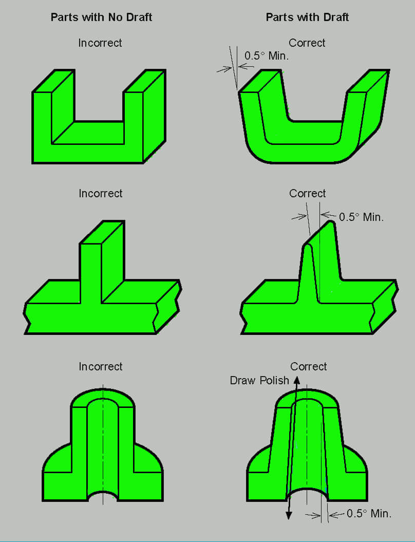
Why Draft Angles Matter:
Draft angles represent small tapers which appear on straight walls and features. They’re a must. The cooling of plastic leads to shrinkage which causes the mold to become gripped. The absence of tapers creates an impossible situation which leads to equipment breakdown. The small incline on the part surface allows for a smooth exit which prevents both surface markings and dimensional deformation. The process becomes faster and the ejection force decreases when draft angles are applied.
What Affects Draft Angles?
Plastic materials that contract heavily need mold angles that are wider. Plastic materials generate a stronger grip with the mold during cooling. The stickiness of rough textured items increases with surface detail. Each tiny increase in surface texture depth requires you to add 1 to 1.5 degrees more draft angle. Polished parts? The design might succeed with only 0.5 degrees of draft. Depth in walls or ribs determines how well they will grip the mold. Extra draft of 1 degree should be added for each new inch of part depth.
How Much Draft to Use?
A minimum wall draft of 0.5 degrees should be applied to straight surfaces. Usually, 1 to 2 degrees works fine. The roughness of parts requires draft angles ranging between 3 and 5 degrees. The best practice when working with soft plastics is to provide draft even though they may tolerate lower angles. Using draft on a mold base is similar to applying oil to a baking pan because prevention is better than having objects stick.
Draft for Ribs and Holes:
Ribs need 0.5 to 1.5 degrees of draft per side. Deeper or textured ones need more. Holes need it too, especially on the inside walls, to slide off the mold pins. Sometimes, for tight fits, tiny undrafted crush ribs inside holes deform just enough to hold tight without needing much draft.
Mixing Ribs, Holes, and Draft Together
Ribs and Holes Working as a Team:
Ribs create influence on holes while holes modify the structure of ribs. The introduction of ribs helps strengthen areas which are close to holes since holes remove specific areas of material. Placing holes directly on rib junctions should be avoided because excess plastic accumulation leads to sink marks.
The incorporation of ribs in injection molding allows better hole filling through directed plastic material distribution. A support system functions similar to this design method because everything requires balance to work properly.
Draft for Both Features:
Make sure ribs and holes near each other have enough draft. Deep features close together might need a bit more slant to pop out of the mold without a fight. It’s like making sure two puzzle pieces don’t jam when you pull them apart.
Real Examples to Learn From:
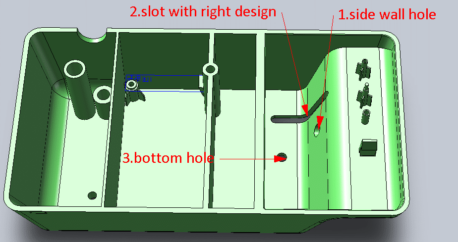
A plastic gear with shaft-attaching features serves as a good example. The small draft opening on the center hole allows the mold to release while crush ribs inside form a tight grip on the shaft through slight bending. The gear’s surface contains ribs that enhance strength and utilizes draft angles for simple unfastening. Plastic boxes demonstrate another case where screw holes exist in bosses. The draft angles on each piece are combined with ribs that join bosses to walls to provide support while thicknesses are managed for surface quality. It’s all about planning ahead.
Quick Design Rules to Remember
- The thickness of walls should remain constant all across the structure. All changes in wall thickness should be done through gradual transitions.
- Inside corners of the mold require a curved shape with dimensions between 0.5 to 0.75 times wall thickness while outside corners need a curved shape of about 1.5 times wall thickness.
- Choose your plastic materials according to their strength and shrinkage characteristics as well as their exposure environment.
- Plan the mold release method and splitting points at the beginning of the design process.
- Ribs must have 50-75% wall thickness while remaining 2.5-3 times shorter than their thickness and being spaced two times apart with a curved base at 0.5-1.5 degrees draft.
- The design requirements specify holes must be at least one diameter away from the edges with blind holes extending 2-4 times their width and through holes extending 3-10 times their width. Bosses and ribs should be added for strength enhancement.
- Draft: Minimum 0.5 degrees, usually 1-2 degrees. More for texture or depth. Match material needs.
Wrapping Up: Build Strong, Easy-to-Make Parts
The process of designing for injection molding requires multiple considerations. All parts of the design system including ribs and holes and draft angles interact with each other. A complete solution requires solving the combination of wall thickness and material selection along with mold splitting.
All elements in the team affect and influence each other in the design process. Producing the product should begin with an easy-to-manage process. The production process becomes more efficient because this reduces the need for repairs and postponements as well as the number of defective parts.
You can consult with professionals who work with molding or use design tools to obtain useful recommendations. The final goal combines both functional requirements of the part with its manufacturing quality needs. Is there a design you need help with ,or do you have a design question? I’m all ears!