Designing Bosses for Injection Molding: A Complete Guide
Designing bosses for injection molding means thinking about several things so the part is strong, can be molded easily and looks good. Here you’ll find a complete guide:
Designing Bosses for Injection Molding
Interactive reference: anatomy, boss types, screw details, defects, and material guidelines
| Boss wall (t) | 0.5 - 0.6 x T |
| OD | 2 x screw diameter |
| Max height | ≤ 3 x OD |
| Draft angle | 0.5 - 1 deg per side |
| Base fillet (R) | ≥ 0.25 x T |
| Coring depth | ≥ 2/3 boss height |
- →Pilot hole ID = screw major dia minus one thread depth
- →Thread engagement = 2x to 2.5x screw diameter
- →Add 0.5 mm chamfer at top for screw entry
- →Boss OD = 2x screw major diameter
- →Core the boss from below to eliminate thick sections
- →Hole ID = insert OD (press fit after insertion)
- →Boss OD = insert OD + 2x nominal wall
- →Allow 0.1-0.2 mm radial clearance for knurls
- →Insertion depth at least 1.5x insert length
- →Pre-placed metal inserts need uniform wall around them
- →Boss wall 0.6-0.8x T to resist insert expansion
- →Add undercuts or knurls on insert for retention
- Keep boss wall at 50-60% of nominal wall thickness
- Use gussets or ribs to reinforce tall bosses
- Core bosses from the underside (non-cosmetic surface)
- Add draft of 0.5-1 deg on inner and outer surfaces
- Place bosses away from external corners to ease flow
- Use a fillet radius at the base (min 0.25x T)
- Offset bosses from walls by at least 2x T
- Make boss wall equal to or thicker than the base wall
- Attach bosses directly flush to side walls (use a thin rib)
- Exceed 3x OD for unsupported boss height
- Forget to core - solid bosses always cause sink
- Place bosses too close together (min 2x OD center-to-center)
- Use sharp corners at the base (stress concentrators)
- Ignore mold draft - zero-draft bosses damage the tool
| Parameter | Recommended | Notes |
|---|---|---|
| Boss wall thickness | 0.5 - 0.6 x T | T = nominal part wall thickness |
| Boss OD | 2.0 x screw dia | 2.5x for glass-filled materials |
| Max height | ≤ 3 x OD | Use gussets above 2x OD |
| Draft angle | 0.5 - 1 deg per side | Both inner and outer surfaces |
| Base fillet radius | ≥ 0.25 x T | Larger radii improve flow and strength |
| Coring depth | ≥ 2/3 boss height | Core from non-cosmetic side |
| Rib / gusset thickness | 0.5 x T | Thicker ribs cause sink on opposite face |
| Boss-to-wall offset | ≥ 2 x T | Connect via rib if closer |
| Boss-to-boss spacing | ≥ 2 x OD c-t-c | Prevents merged thick sections |
1. How and Where a Button is Used
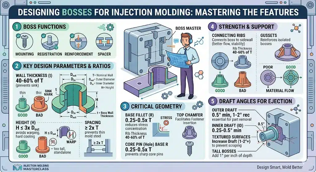
Function: Bosses are normally cylindrical shapes put in place to attach screws, threaded inserts or to act as guides for mating parts.
Spreading out the bosses prevents the stress from focusing in one area which could result in part failure. Distribute your advertisements in ways that make sense.
Bosses Should Be Close to Walls: Adding bosses near thick walls or connecting them to sidewalls with ribs or gussets helps them become stronger and more stable. Don’t put bosses in spots that will create a thick space that is hard to keep cool.
Whenever it is convenient, put bosses on the inside of the part so they are less likely to get damaged.
2. Wall Thickness
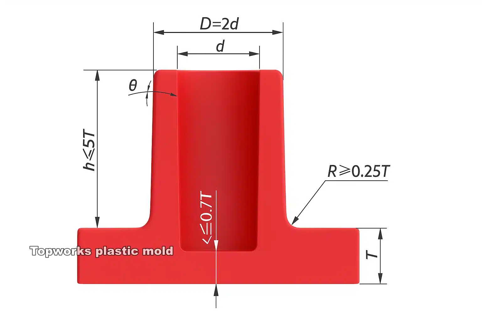
The thickness of a boss should usually be between 40% and 60% of the nominal wall thickness in the part. Always do this to stop the opposite side from forming sink marks.
Don’t Get Sink Marks: As metal cools, thick areas take more time than thin areas. If the boss wall is too thick compared to the rest, it will shrink more, forming a depression on the part’s top surface that shows.
Building vs. Breaking: While bosses should have enough wall to support fasteners, going past 60% thickness greatly increases the likelihood of sink marks and hollow spots. You might need to use ribs or gussets if the boss isn’t strong enough when you only thicken the wall.
Different plastics have different amounts of shrinkage. Materials subject to greater shrinkage often need the boss walls to be even thinner than normal.
3. length
A boss should usually be no more than three times as tall as its outer diameter. Thick bases on tall bosses may cause cooling problems, lead to sink marks and increase the time it takes to make the part. The inside of the boss which is formed by tall, thin core pins, is not easy to cool and can bend during the molding process.
Maintain Proper Engagement: Be sure the boss’s height allows plenty of engagement with the screw (at least 60% of its thread). The OD of the boss should be between 2.0 and 2.5 times the diameter of the screw or insert it will fit. You end up with strength that isn’t overbuilt.
4. Draft Angles
It is important for ejection that the inner and outer walls of the boss both have a slight taper (draft). A lack of draft may produce drag marks, harm the part or harm the mold.
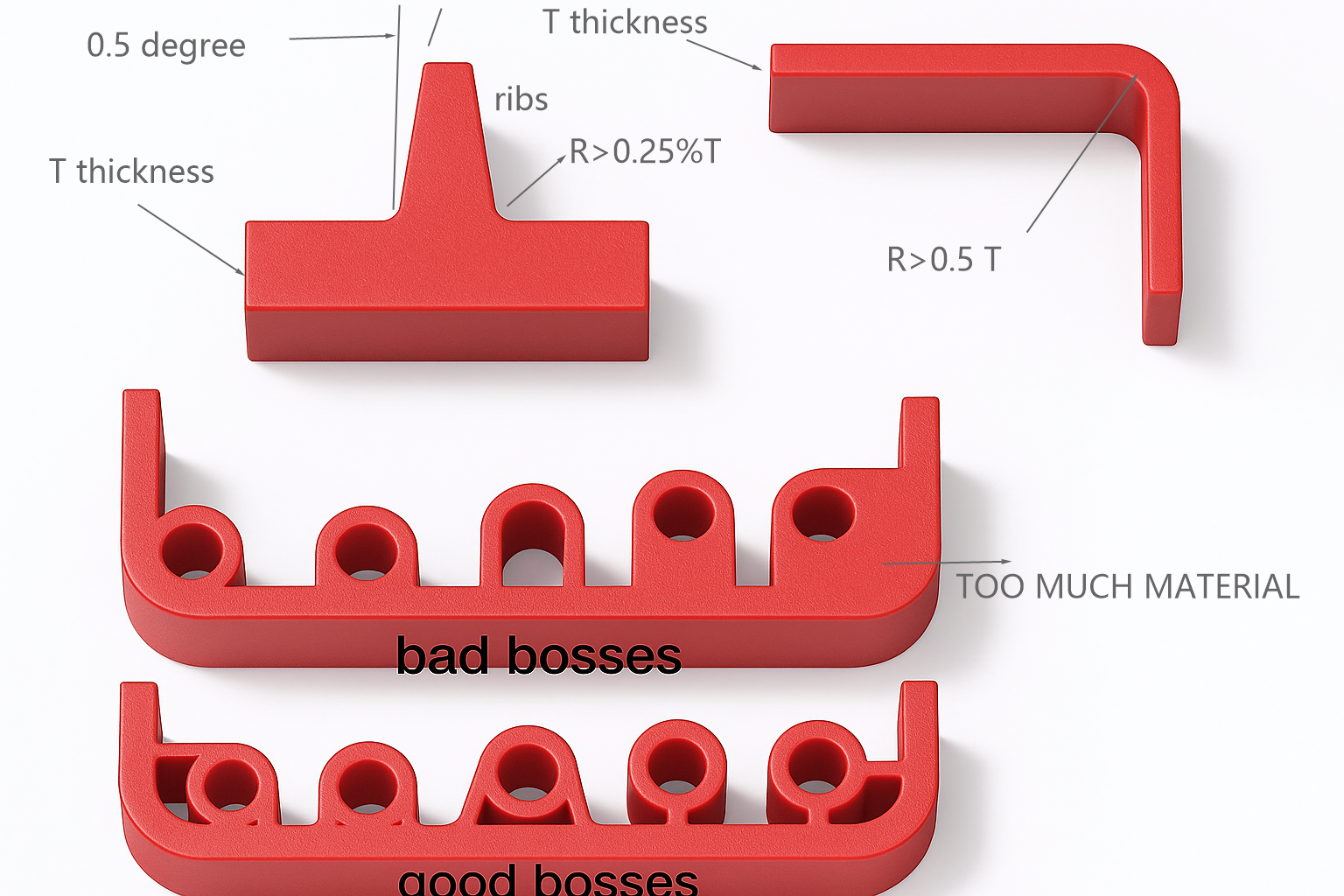
- A minimum of 0.5 degrees is generally suggested for Outer Diameter (OD) Draft. A lot of sources recommend setting your oven to 1 to 2 degrees for most recipes.
- Recommended ID draft: The minimum should be between 0.25 and 0.5 degrees. If the part has a textured surface, increase the draft angle by 1 or 2 degrees or more to ensure it won’t scrape.
- Softer, bendy materials may reduce draft somewhat more than rigid and highly shrinking ones. If your boss is tall, you’ll need to draft more than usual. A rule of thumb is to add another degree for every inch of depth.
5. Support for Your Garment Comes from Ribs and Gussets
A better way than making boss walls thick is to use ribs or gussets that join the boss to surrounding walls or reinforce standalone bosses. Because of this, the surface is more rigid and the material moves better, but sink marks are avoided. The ribs beneath the bosses must also have a wall thickness that is 40-60% of the nominal wall thickness of the main structure. Link the ribs to the outline of the boss outer edge. Don’t leave a thick part of the rib at the boss base when trimming it.
6. The Terms Used to Describe the Outside Shape of a Leg Joint are Radii and Chamfers
Include a wide radius at the bottom of the boss, where it touches the part it’s attached to. A radius that is between 0.25 and 0.5 times the nominal wall thickness is suggested. As a result, stress does not accumulate in one area and material flow is smoother. Don’t let the radii become too big and cause your parts to have thick sections.Add a radius or chamfer at the place where the boss hole meets the counterbore. It helps to start the fastener and lower the amount of pressure on the core pin.Avoid using sharp corners in bosses since they collect stress and may stop materials from flowing properly.
7. How Far Apart Are the Bosses?
If you have more than one boss, leave at least 2 times the wall thickness of the part between them. As a result, cooling is better controlled, the steel does not become too thin in the mold and weld lines are less likely to be a problem.
8. How to Prevent Sink Marks
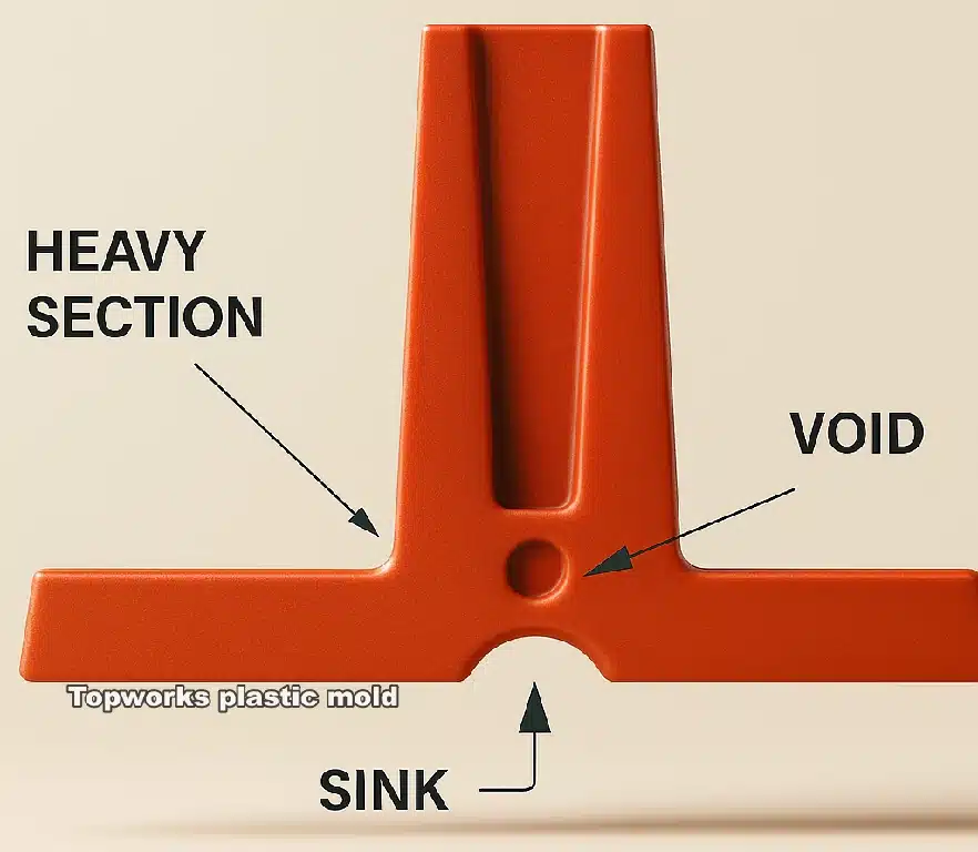
Stick to the rule of having bosses and supporting ribs at least 40% but not more than 60% of the tube’s wall thickness.Thick bosses that rely on strength should be cored out in the base or underside to ensure the walls are uniform. Occasionally, a small groove across the bottom of the boss will make it easier to slide the pin.Place the gate so that bosses won’t damage the opposite side of your sculpture. Pushing into a thicker part of the design can sometimes help crowd the area, yet this needs to be thought through to keep other problems away.
Setting the right molding conditions (temperature of the melt, pressure used for packing, amount of time for packing and temperature of the mold) helps to reduce sink.
9. Material Selection
Keep in mind the shrinkage rate of the plastic, as it can result in sink marks and trouble with the object’s measurements.
The material should be strong enough, stiff enough and able to withstand the temperatures required for the boss’s purpose. The type of fastener such as a self-tapping screw or threaded insert can decide the right material to use and the details of the boss hole.
10. The Site of Gates and How They Are Vented
Do not put a gate on top of or close to a critical feature such as a boss, because it can cause problems with its look or strength. Still, sometimes keeping the gate near the boss helps guarantee the boss will fill. Bosses which are formed by blind holes in the mold may need venting (by using vent pins at the edge) to let gases escape while the mold is being filled, avoiding both short shots and burns.
What Should Bosses Check in Their Designs?
- Thickness of part walls should be within 40-60% of their nominal value?
- Measure the height; is it less than 3 times the outer diameter?
- Does the object’s draft have to be at least 0.5 degrees for texture/depth?
- ID Draft: More than 0.25 degrees?
- For a Base Radius, use a range of 0.25 to 0.5 times the wall thickness from the nominal size?
- Support: Gussets or ribs added to tall or single bosses? About 40-60% of the wall is covered by ribs.
- For walls built together, is there at least 2x the wall thickness separating each one?
- A review of sink mark risk was done and solutions were found?
- Properties of Materials: Can this material be used and fastened together?
- Under these conditions, does the draft and radius help with ejection and lower stress?
When you use these tips, your bosses will have the needed strength and flexibility for your plastic part and will be less likely to have defects after manufacture. You should always advise with a professional mold designer or injection molding supplier when developing your design.
| Parameter | Recommended Value | Reason |
|---|---|---|
| Thickness (t) | 0.5 ~ 0.7 times product wall thickness (T) | Too thick can cause surface sink marks; too thin provides insufficient strength. |
| Height (h) | 2 ~ 3 times thickness (t), not exceeding 5 times | Too high may cause warping or uneven cooling; consider mold depth. |
| Spacing | At least 2 times wall thickness (T) | Ensures even filling and avoids weak spots in thin areas. |
| Bottom Fillet Radius | At least 0.25 ~ 0.5 times thickness (t) | Reduces stress concentration, improves strength, and enhances flow. |
