


Was ist das Spritzgießen von Kunststoffen?
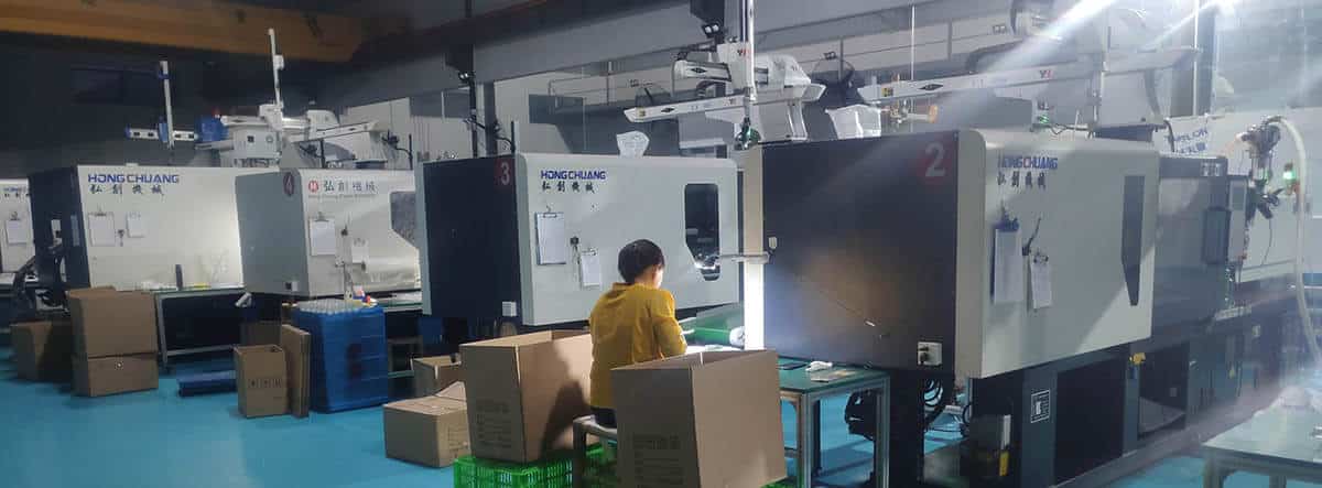
Beim Spritzgießen von Kunststoffen werden Formen verwendet, um Teile durch Einspritzen von Material herzustellen. Die kunststoffverarbeitende Industrie nutzt dieses Verfahren für die Herstellung von Bauteilen, weil es präzise Ergebnisse und hohe Effizienz liefert und die Möglichkeit bietet, komplizierte Formen herzustellen. Hersteller in der Automobil-, Konsumgüter- und Medizintechnikbranche bevorzugen diese Methode, weil sie Kosteneffizienz mit Skalierbarkeit verbindet.
What Is Injection Molding?
7 key points explaining injection molding clearly
Injection molding is a manufacturing process used to produce plastic parts by injecting molten plastic into a precision mold under high pressure.
After the plastic cools and solidifies, the mold opens and the finished part is ejected. This process allows manufacturers to produce large quantities of identical parts with high accuracy and consistency.
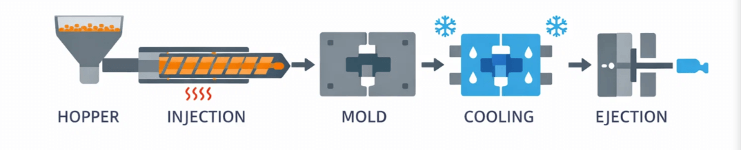
The injection molding process consists of four main steps:
Clamping: The mold is closed and clamped tightly by the machine.
Injection: Molten plastic is injected into the mold cavity through a runner and gate system.
Cooling: The plastic cools and solidifies into the desired shape.
Ejection: The mold opens and ejector pins push the finished part out.
Injection molding commonly uses thermoplastics, including:
ABS: Strong, impact-resistant, good surface finish.
Polypropylen (PP): Lightweight, chemical resistant, flexible.
Polycarbonat (PC): Transparent and high impact strength.
Nylon (PA): High strength and wear resistance.
Injection molding is ideal for producing:
• High-volume plastic parts
• Complex geometries with tight tolerances
• Parts with consistent dimensions and surface finish
• Components used in automotive, medical, electronics, and consumer products
Key advantages include:
• High production efficiency
• Excellent repeatability and accuracy
• Low material waste
• Ability to mold complex shapes
• Low per-part cost at high volumes
Despite its benefits, injection molding has some limitations:
• High initial mold cost
• Long tooling lead time
• Design changes after mold fabrication can be expensive
• Not economical for very low production volumes
Injection molding is the best choice when you need:
• Medium to high production volumes
• Tight tolerances and consistent quality
• Durable plastic parts with good surface finish
• Scalable manufacturing for long-term production
The Injection Molding Process
Interactive visual reference covering every phase, machine component, parameter, defect, and material
| Parameter | Typical range | Effect |
|---|---|---|
| Barrel zone 1 (feed) | 160 - 220 C | Lower temp prevents bridging in feed throat |
| Barrel zone 2 (compression) | 200 - 260 C | Progressive melting of pellets |
| Barrel zone 3 (metering) | 220 - 300 C | Homogeneous melt temperature |
| Düse | 210 - 300 C | Prevents cold slugs, drool |
| Mold (coolant) | 20 - 120 C | Controls cooling rate, crystallinity, surface finish |
| Hot runner | Match nozzle zone | Keeps runner system molten, eliminates cold runner waste |
| Parameter | Typical range | Effect |
|---|---|---|
| Einspritzdruck | 500 - 2000 bar | Fills the cavity; higher for thin walls |
| Packing/holding pressure | 40 - 80% of injection | Compensates for shrinkage during cooling |
| Back pressure | 3 - 15 bar | Improves melt homogeneity during screw recovery |
| Clamping force | 1.5 - 5 t/in2 projected area | Prevents mold opening / flash |
| Cavity pressure | 300 - 800 bar | Measured via sensor; indicates fill quality |
| Parameter | Typical range | Effect |
|---|---|---|
| Einspritzgeschwindigkeit | 20 - 150 mm/s | Faster = better fill for thin walls; too fast = jetting |
| Screw RPM | 50 - 200 RPM | Controls plasticizing rate and melt quality |
| Cooling time | 5 - 60 sec | Largest portion of cycle; depends on wall thickness |
| Cycle time | 10 - 120 sec | Total: clamp + inject + pack + cool + open + eject |
| Mold open/close speed | Variable (fast/slow) | Fast in center, slow at start/end for protection |
| Parameter | Beschreibung | Why it matters |
|---|---|---|
| Shot size | Volume of melt per cycle | Must fill cavity + runner + cushion |
| Cushion | 2 - 6 mm of melt ahead of screw | Ensures packing pressure transmission |
| V/P switchover point | Position or pressure at transition | Controls switch from velocity to pressure phase |
| Screw decompression | 1 - 5 mm pullback after recovery | Prevents drool from nozzle |
| Ejector stroke | Part-dependent | Must clear part from core without damage |
- Dry hygroscopic materials (nylon, PC, PET) before processing
- Use scientific molding: decouple fill, pack, and hold phases
- Perform cavity balance studies on multi-cavity molds
- Monitor cushion consistency shot-to-shot
- Document a process window with DOE
- Use cavity pressure sensors for quality feedback
- Purge thoroughly when changing materials or colors
- Maintain consistent mold temperature with TCU
- Rely solely on machine hydraulic pressure for quality control
- Skip material drying - moisture causes splay and degradation
- Use maximum injection speed without profiling
- Ignore cushion size - zero cushion means no pack
- Over-pack parts to fix short shots (address root cause)
- Change multiple parameters at once during troubleshooting
- Run without mold protection at low pressure close
- Neglect preventive maintenance on screws and check rings
| Phase | % of cycle | Primary driver | How to reduce |
|---|---|---|---|
| Mold close | 3-5% | Clamp speed, mold protection | Optimize slow/fast positions |
| Injection fill | 5-15% | Injection speed, wall thickness | Increase speed (within limits) |
| Packing/holding | 10-20% | Gate freeze time | Optimize gate size, hold time study |
| Kühlung | 50-70% | Wall thickness, mold temp | Conformal cooling, beryllium copper inserts, reduce wall thickness |
| Mold open + eject | 5-10% | Stroke length, ejector speed | Minimize open stroke, use air poppets |
Tipps zur Gestaltung von Spritzgussteilen

Dank der Skalierbarkeit und Einheitlichkeit des Verfahrens können einfache bis sehr komplizierte Kunststoffspritzgussteile sowie Millionen von identischen Teilen hergestellt werden. Werkzeugbau und Wartung sind teuer, und der Wechsel von Werkzeugen ist eine Herausforderung.
Spritzgegossene Teile: Maximieren Sie ihre Vorteile
- Konsistenz ist der Schlüssel. Achten Sie darauf, dass Ihre Wände überall gleich dick sind. Die Wände sollten im Durchschnitt 2-3 mm dick sein. Standard-Spritzgussverfahren empfehlen eine Mindeststärke von 1 mm und eine Höchststärke von 4 mm.
- Glatt übertrumpft scharf. Glätten Sie Wandübergänge, wann immer möglich.
- Entwurf. A Entformungsschräge kann bei der Konstruktion Ihres Teils zu Problemen führen. Das Hinzufügen eines Entformungswinkels zu Ihren Flächen ist hilfreich, um das Teil aus dem Werkzeug zu lösen, kann aber auch Probleme verursachen, insbesondere bei Gegenstücken. Bei unstrukturierten Kernflächen und mindestens drei Grad bei strukturierten Hohlraumflächen wird ein Mindestentformungswinkel von einem Grad empfohlen.
- Wenn möglich, halten Sie sich von Oberflächen mit Nullzug fern. Im Falle einer zugfreien Zone sollten Sie versuchen, diese auf einen Teil der Fläche zu beschränken, nicht auf die gesamte Oberfläche.
- Halten Sie es einfach. Attempt to prevent undercutting (forming an area that cannot be shaped simply by opening and closing the tool). When simple won't work, lifter and slides allow features to be formed that are undercuts in the main pull direction. If so, leave at least 2 to 3 times the width of the feature to allow the lifter or slide to travel.
- Fluss von dick nach dünn. Kunststoff fließt besser durch Merkmale, wenn er von der dickeren zur dünneren Wand fließt, beginnend am Anschnitt (wo der Kunststoff in das Teil fließt, um es zu füllen).
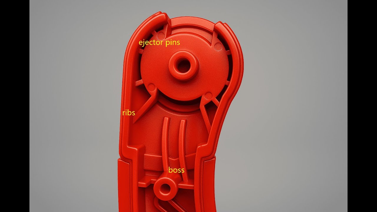
- Es ist schlecht, Waschbecken zu haben (Verdichtungen auf Oberflächen, die dadurch entstehen, dass sich dickere Kunststoffteile beim Abkühlen abschwächen). Es ist wichtig, diese Richtlinien zu befolgen, um das Auftreten von Unreinheiten auf kosmetischen Oberflächen zu minimieren oder zu beseitigen:
- Achten Sie darauf, dass wichtige kosmetische Oberflächen auf der Rückseite keine Anschnitte, Rippen, Schraubdome usw. aufweisen;
- Die Rippenhöhe sollte dreimal geringer sein als die Wandstärke;
- Für Rippenböden sollten 60% oder weniger der Wandstärke verwendet werden.
- Territorien werden durch Bezugspunkte definiert. Um die Schnittstelle und die Interaktion zwischen den Teilen festzulegen, verwenden Sie Bezugspunkte (Merkmale, die als Referenzpunkte für die Teile dienen). Wenn eine Konstruktionsabsicht auf eine Bezugsstruktur abgestimmt ist, kann ein Produkt ordnungsgemäß funktionieren.
- Gegen ein Verhör ist nichts einzuwenden. Unter DFM (Design for Manufacturing) teilt der Gießer sein Verständnis des Entwurfs mit, insbesondere in Bezug auf die Position von Stiften, Anschnitten und Trennlinien (die das Zusammenspiel der Teile beeinflussen können). Hinterfragen Sie das Design anhand von Prüfberichten.
- Erstellen Sie häufig und frühzeitig Prototypen. Heutige Prototyping-Techniken, einschließlich des 3D-Drucks, können die Materialkosten senken, indem sie es ermöglichen, Komponenten und/oder das gesamte Teil zu modellieren, bevor teure Werkzeuge gebaut werden müssen.
Konstruktionsrichtlinien für das Spritzgießen
Essential rules for strong, manufacturable plastic parts. All values reference nominal wall thickness T, hole diameter D, or hole width W.
Geometry
Wanddicke
Inconsistent thickness causes warping and sink marks.
Corner Radii
Reduces stress concentration and improves plastic flow.
Entwurfswinkel
Rippen
Löcher
Add bosses and connecting ribs for reinforcement.
Prozess
Auswahl des Materials
Choice drives required wall thickness and draft angles.
Ejection & Parting
Simplifies mold design and reduces post-processing.
Pros and Cons of Plastic Injection Molding
| Category | Pros (Advantages) | Cons (Disadvantages) |
|---|---|---|
| Accuracy | High precision and repeatability. Capable of producing complex and detailed geometries. | High precision also means errors in design can lead to costly defects. |
| Produktionsgeschwindigkeit | Very fast cycle time (about 15–20 seconds). Ideal for high-volume mass production. | Initial setup and mold design can take weeks or months. |
| Kosteneffizienz | Low cost per unit in large-scale production. Automation reduces labor costs. | High upfront costs for molds, machines, and tooling. |
| Labor Requirements | Mostly automated; fewer operators needed once production starts. | Requires skilled technicians for mold design, setup, and quality control. |
| Vielseitigkeit | Suitable for a wide range of products, from small electronic parts to large automotive components. | Limited by machine size and material constraints. |
| Nachhaltigkeit | Minimal material waste during production. Some plastics can be recycled and reused. | Difficult to recycle complex or multi-material molded parts. |
| Product Quality | Consistent quality across large production runs. | Possible defects such as warping, sink marks, or flash if process is not optimized. |
| Scalability | Excellent for large-scale and continuous manufacturing. | Not cost-effective for small batch or low-volume production. |
Die 6 verschiedenen Arten des Kunststoffspritzgießens
Es gibt verschiedene Arten von Kunststoff-Formteilen, die jeweils ihre eigenen Merkmale und Vorteile haben. Hier sind sechs gängige Arten des Kunststoffspritzgießens:
- Spritzgießen: Dies ist eine gängige Methode zur Herstellung großer Mengen von Kunststoffteilen. Dabei wird geschmolzener Kunststoff in einen Formhohlraum gespritzt, wo er abkühlt und in der gewünschten Form erstarrt. Das Spritzgießen ist schnell und effizient und ermöglicht die Herstellung hochpräziser und gleichmäßiger Teile.
- Blasformen: Dieses Verfahren wird zur Herstellung hohler Kunststoffteile wie Flaschen und Behälter verwendet. Dabei wird der Kunststoff erhitzt, bis er geschmeidig ist, und dann mit Luftdruck in einen Formhohlraum geblasen. Blasformen wird häufig für große, komplexe Teile mit dünnen Wänden verwendet.
- Strangpressen: Bei diesem Verfahren wird der Kunststoff geschmolzen und durch eine Düse gepresst, um eine kontinuierliche Form zu erzeugen, z. B. ein Rohr oder eine Platte. Die entstandene Form wird dann auf die gewünschte Länge geschnitten. Das Strangpressen wird häufig für Produkte mit konstantem Querschnitt, wie Rohre und Schläuche, verwendet.
- Thermoformung: Bei diesem Verfahren wird eine Kunststoffplatte erhitzt, bis sie biegsam ist, und dann mit Hilfe von Vakuumdruck über einer Form geformt. Das Thermoformen wird zur Herstellung einer breiten Palette von Produkten verwendet, darunter Becher, Schalen und Verpackungsmaterial.
- Rotationsgießen: Bei diesem Verfahren wird eine Form mit pulverförmigem Kunststoff gefüllt und dann in einem Ofen gedreht, um den Kunststoff gleichmäßig zu verteilen. Die Form wird dann abgekühlt und das entstandene Teil wird entnommen. Rotationsgießen wird häufig für große, hohle Teile mit komplexen Formen verwendet.
- Formpressen: Bei diesem Verfahren wird eine Kunststoffladung erhitzt und unter hohem Druck in einen Formhohlraum gepresst. Das Formpressen wird in der Regel für die Produktion mittlerer bis hoher Stückzahlen von Teilen mit einfachen Formen und gleichmäßigen Wandstärken verwendet.
