


qué es el moldeo por inyección de plásticos
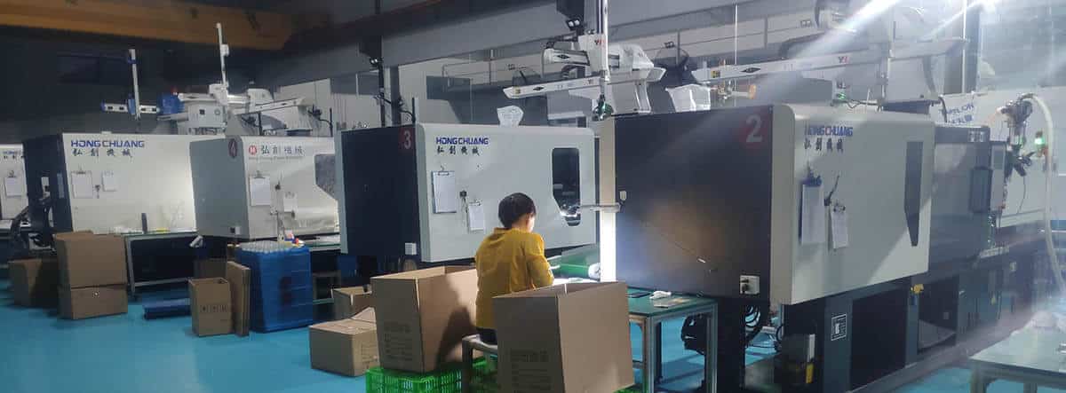
El proceso de moldeo por inyección de plásticos implica el uso de moldes para crear piezas mediante la inyección de material. La industria de fabricación de plásticos utiliza este método para la creación de componentes porque ofrece resultados de precisión y alta eficiencia junto con la capacidad de crear formas intrincadas. Los fabricantes de los sectores de automoción, bienes de consumo y dispositivos médicos prefieren este método porque combina la rentabilidad con la escalabilidad.
What Is Injection Molding?
12 expert answers covering process, materials, cost, cycle time, defects & design
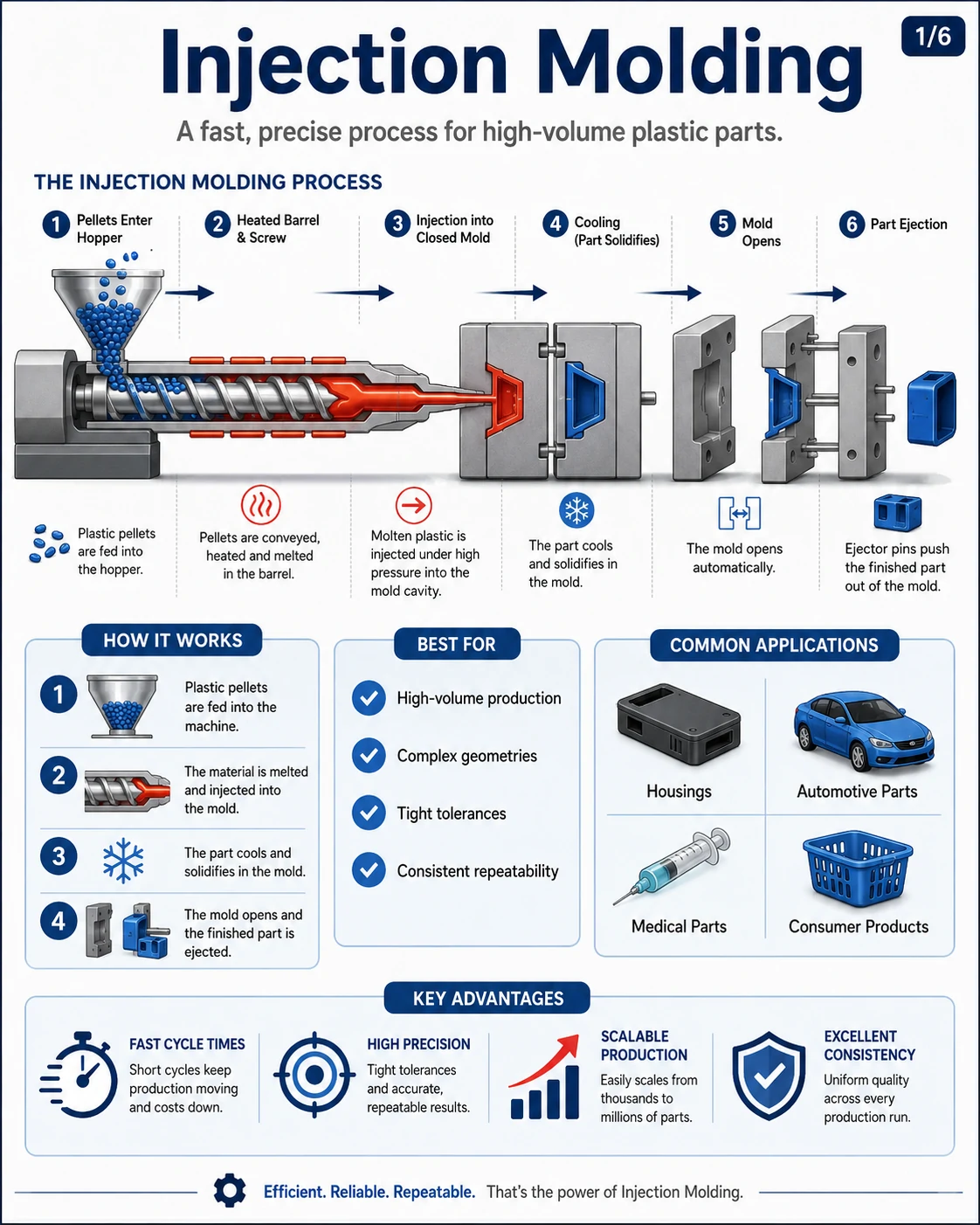
Injection molding is a manufacturing process that produces plastic parts by injecting molten thermoplastic into a precision steel or aluminum mold under high pressure, typically between 500–2000 bar. After the plastic cools and solidifies — usually within 15–60 seconds — the mold opens and ejector pins push the finished part out.
It is the most widely used plastic manufacturing method worldwide, capable of producing millions of identical parts with tolerances as tight as ±0.05 mm. Industries that rely heavily on injection molding include automotive, medical devices, consumer electronics, packaging, and household goods.
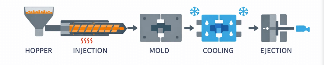
The injection molding process consists of six phases executed in a continuous cycle:
1. Clamping: The two mold halves close and the clamping unit applies tonnage (typically 1.5–5 tons per square inch of projected part area) to keep them sealed during injection.
2. Injection: A reciprocating screw pushes molten plastic into the mold cavity through a runner and gate system at pressures of 500–2000 bar.
3. Packing (Holding): Additional pressure (40–80% of injection pressure) compensates for material shrinkage as the part begins to cool.
4. Cooling: The plastic solidifies inside the mold. This phase consumes 50–70% of total cycle time and depends on wall thickness and material.
5. Mold Open: The clamping unit retracts and separates the mold halves.
6. Ejection: Ejector pins push the finished part out of the cavity, completing the cycle.
Total cycle time ranges from 10 to 120 seconds depending on part complexity, wall thickness, and material.
Injection molding primarily uses thermoplastics, which can be melted and re-solidified repeatedly. The most common materials and their key properties:
| Material | Melt Temp | Key Properties |
|---|---|---|
| ABS | 220–260°C | Impact-resistant, good finish |
| Polipropileno (PP) | 200–280°C | Lightweight, chemical resistant |
| Policarbonato (PC) | 280–320°C | Transparent, high impact strength |
| Nylon (PA6/PA66) | 250–290°C | High strength and wear resistance |
| POM (Acetal) | 190–210°C | Dimensional stability, low friction |
| TPE / TPU | 180–230°C | Soft-touch, flexible elastomers |
Material selection drives required wall thickness, draft angles, shrinkage allowance (0.4%–2.5%), and mold cooling design.
Injection molding is ideal for parts that meet these criteria:
- Production volume: Generally cost-effective above 10,000 units per design
- Complex geometries: Undercuts, threads, snap fits, and living hinges in a single shot
- Tight tolerances: Down to ±0.05 mm for precision components
- Wall thickness: Typically 1–4 mm, ideally uniform at 2–3 mm
- Consistent surface finish: From high-gloss polish to textured finishes (SPI A-1 to D-3)
Typical applications include automotive interior trim, medical syringes, electronic enclosures, bottle caps, gears, and consumer product housings.
Key advantages of injection molding include:
- Fast cycle times: 15–30 seconds for small parts, enabling millions of units per year per cavity
- High repeatability: Less than 0.1% dimensional variation across millions of parts
- Low material waste: Typically under 5%, with sprues and runners regrindable
- Complex geometries: Multiple features molded in a single shot, eliminating assembly
- Low per-part cost at scale: Often $0.01–$1.00 per part depending on size and material
- Automation-friendly: Robotic part removal and integration into assembly lines
Despite its strengths, injection molding has notable limitations:
- High mold cost: Tooling typically ranges from $3,000 for simple aluminum molds to $100,000+ for multi-cavity hardened steel molds
- Long lead time: Mold design and fabrication usually take 4-10 semanas
- Expensive design changes: Mold modifications cost $500–$10,000 depending on complexity
- Not economical for low volumes: Below ~1,000 parts, 3D printing or CNC machining is often cheaper
- Design restrictions: Requires draft angles, uniform wall thickness, and avoidance of undercuts where possible
Injection molding is the best choice when your project requires:
- Medium to high production volumes (typically 10,000+ units)
- Tight, repeatable tolerances across long production runs
- Durable plastic parts with good surface finish and structural integrity
- Long-term scalability — one mold can produce millions of parts over 5–10+ years
- Complex shapes that would require multiple operations with other methods
For prototypes or runs under 1,000 parts, consider Impresión 3D o Mecanizado CNC instead. For very large hollow parts, rotational molding o moldeo por soplado may be more economical.
Injection molding cost has two main components: tooling cost (one-time) and per-part cost (recurring).
Mold tooling cost:
- Simple prototype mold (aluminum, single cavity): $1,000–$5,000
- Standard production mold (P20 steel, 1–2 cavities): $5,000–$30,000
- High-volume mold (H13 hardened steel, multi-cavity): $30,000–$100,000+
- Complex mold with hot runners, slides, lifters: $50,000–$200,000+
Per-part cost typically ranges from $0.01 to $5.00 and depends on:
- Material cost (e.g., PP ~$1.50/kg, PC ~$4.00/kg)
- Cycle time (longer cycle = higher cost)
- Part weight and machine tonnage required
- Labor and overhead rates (China is typically 30–50% cheaper than US/EU)
Break-even versus 3D printing is usually around 500–1,000 units; versus CNC machining around 100–500 units.
Total injection molding cycle time typically ranges from 10 to 120 seconds, with most consumer parts cycling in 15–45 seconds.
Cycle time breakdown by phase:
| Phase | % of Cycle | Typical Duration |
|---|---|---|
| Mold close | 3–5% | 0.5–2 sec |
| Injection fill | 5–15% | 1–5 sec |
| Packing / holding | 10–20% | 2–10 sec |
| Refrigeración | 50–70% | 5–60 sec |
| Mold open + eject | 5–10% | 1–5 sec |
Cooling time formula: t ≈ s² ÷ (π² × α), where s is max wall thickness in mm and α is the polymer’s thermal diffusivity. Practical rule of thumb: roughly 2–3 seconds of cooling per mm of wall thickness for semi-crystalline resins. Because cooling time scales with the square of wall thickness, a 4 mm wall takes roughly four times longer to cool than a 2 mm wall.
Cycle time can be reduced by using conformal cooling channels, beryllium copper inserts, thinner wall designs, and optimized mold temperature control.
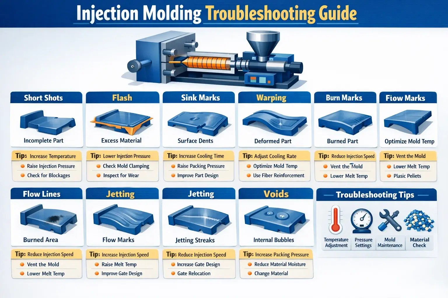
Most injection molding defects fall into three severity categories with identifiable root causes:
Critical defects:
- Short shots (incomplete fill) — caused by insufficient injection pressure, low melt temperature, or undersized gates
- Flash (excess material at parting line) — caused by insufficient clamping force or excessive injection pressure
- Burn marks — trapped air compresses and ignites (diesel effect); fix with better venting
Major defects:
- Marcas de hundimiento (surface depressions) — insufficient packing pressure over thick sections like ribs or bosses
- Warpage (part distortion) — non-uniform cooling or unbalanced flow
- Weld/knit lines — weak bonds where two melt fronts meet; fix by raising melt temp or relocating gates
Minor defects:
- Jetting — snake-like surface pattern from melt squirting through gate too fast
- Silver streaks (splay) — from moisture in material; fix with proper drying
- Flow marks — wavy lines from melt hesitation; fix with higher injection speed or mold temp
Most defects are solved through scientific molding: decoupling fill, pack, and hold phases, then optimizing each independently using a Design of Experiments (DOE).
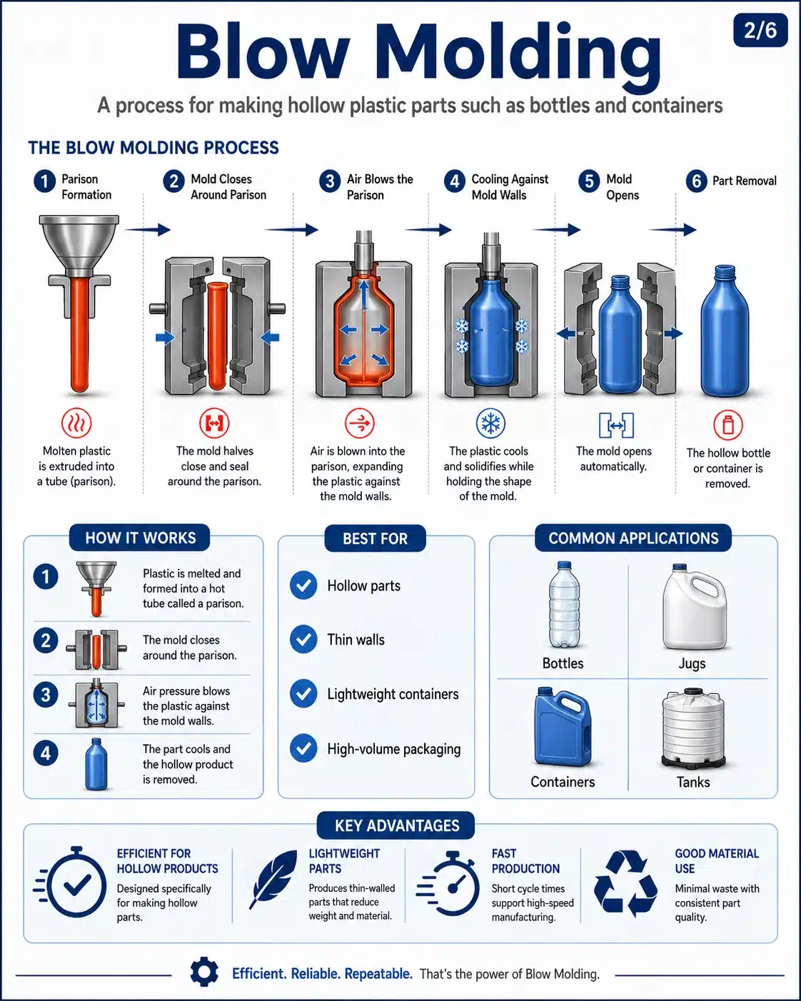
Both processes use molten plastic and molds, but they create fundamentally different part types:
| Característica | Moldeo por inyección | Moldeo por soplado |
|---|---|---|
| Part type | Solid parts | Hollow parts |
| Cómo funciona | Molten plastic injected into closed mold | Heated plastic inflated with air inside mold |
| Wall thickness | 1–4 mm, uniform | Thin, variable walls |
| Lo mejor para | Gears, housings, brackets, connectors | Bottles, containers, tanks, fuel tanks |
| Tooling cost | Higher ($5K–$100K+) | Lower ($3K–$50K) |
| Cycle time | 10–120 sec | 10–30 sec |
| Tolerancia | ±0.05 mm | ±0.5 mm |
Rule of thumb: If your part is hollow and you can pour liquid into it (bottle, jerry can, fuel tank), use blow molding. If your part is solid or has functional features like ribs, bosses, or snap fits, use injection molding.
The ideal wall thickness for injection molded parts is 2–3 mm, with a strict rule of uniformity throughout the part. Acceptable range is 1 mm minimum to 4 mm maximum.
Recommended wall thickness by material:
| Material | Recommended Range |
|---|---|
| ABS | 1.2–3.5 mm |
| Polipropileno (PP) | 0.8–3.8 mm |
| Policarbonato (PC) | 1.0–3.8 mm |
| Nylon (PA) | 0.8–3.0 mm |
| POM (Acetal) | 0.8–3.0 mm |
Critical design rules:
- Uniformity: Wall thickness variation should be under 25% to prevent warpage and sink marks
- Rib thickness: 50–60% of the wall it connects to
- Rib height: Maximum 3× the wall thickness
- Transitions: Use gradual tapers — never abrupt thickness changes
- Inside corner radius: 0.5–0.75× the wall thickness to reduce stress concentration
Thicker walls increase cycle time exponentially (cooling time scales with the square of wall thickness), so thinner uniform walls are always preferred where strength permits.
The Injection Molding Process
Interactive visual reference covering every phase, machine component, parameter, defect, and material
| Parameter | Typical range | Effect |
|---|---|---|
| Barrel zone 1 (feed) | 160 - 220 C | Lower temp prevents bridging in feed throat |
| Barrel zone 2 (compression) | 200 - 260 C | Progressive melting of pellets |
| Barrel zone 3 (metering) | 220 - 300 C | Homogeneous melt temperature |
| Boquilla | 210 - 300 C | Prevents cold slugs, drool |
| Mold (coolant) | 20 - 120 C | Controls cooling rate, crystallinity, surface finish |
| Hot runner | Match nozzle zone | Keeps runner system molten, eliminates cold runner waste |
| Parameter | Typical range | Effect |
|---|---|---|
| Presión de inyección | 500 - 2000 bar | Fills the cavity; higher for thin walls |
| Packing/holding pressure | 40 - 80% of injection | Compensates for shrinkage during cooling |
| Back pressure | 3 - 15 bar | Improves melt homogeneity during screw recovery |
| Clamping force | 1.5 - 5 t/in2 projected area | Prevents mold opening / flash |
| Cavity pressure | 300 - 800 bar | Measured via sensor; indicates fill quality |
| Parameter | Typical range | Effect |
|---|---|---|
| Velocidad de inyección | 20 - 150 mm/s | Faster = better fill for thin walls; too fast = jetting |
| Screw RPM | 50 - 200 RPM | Controls plasticizing rate and melt quality |
| Cooling time | 5 - 60 sec | Largest portion of cycle; depends on wall thickness |
| Cycle time | 10 - 120 sec | Total: clamp + inject + pack + cool + open + eject |
| Mold open/close speed | Variable (fast/slow) | Fast in center, slow at start/end for protection |
| Parameter | Descripción | Why it matters |
|---|---|---|
| Shot size | Volume of melt per cycle | Must fill cavity + runner + cushion |
| Cushion | 2 - 6 mm of melt ahead of screw | Ensures packing pressure transmission |
| V/P switchover point | Position or pressure at transition | Controls switch from velocity to pressure phase |
| Screw decompression | 1 - 5 mm pullback after recovery | Prevents drool from nozzle |
| Ejector stroke | Part-dependent | Must clear part from core without damage |
- Dry hygroscopic materials (nylon, PC, PET) before processing
- Use scientific molding: decouple fill, pack, and hold phases
- Perform cavity balance studies on multi-cavity molds
- Monitor cushion consistency shot-to-shot
- Document a process window with DOE
- Use cavity pressure sensors for quality feedback
- Purge thoroughly when changing materials or colors
- Maintain consistent mold temperature with TCU
- Rely solely on machine hydraulic pressure for quality control
- Skip material drying - moisture causes splay and degradation
- Use maximum injection speed without profiling
- Ignore cushion size - zero cushion means no pack
- Over-pack parts to fix short shots (address root cause)
- Change multiple parameters at once during troubleshooting
- Run without mold protection at low pressure close
- Neglect preventive maintenance on screws and check rings
| Phase | % of cycle | Primary driver | How to reduce |
|---|---|---|---|
| Mold close | 3-5% | Clamp speed, mold protection | Optimize slow/fast positions |
| Injection fill | 5-15% | Injection speed, wall thickness | Increase speed (within limits) |
| Packing/holding | 10-20% | Gate freeze time | Optimize gate size, hold time study |
| Refrigeración | 50-70% | Wall thickness, mold temp | Conformal cooling, beryllium copper inserts, reduce wall thickness |
| Mold open + eject | 5-10% | Stroke length, ejector speed | Minimize open stroke, use air poppets |
Consejos de diseño para el moldeo por inyección

Es posible fabricar desde piezas de plástico moldeadas por inyección sencillas hasta extremadamente complicadas, así como millones de artículos idénticos, gracias a la escalabilidad y uniformidad del proceso. Construcción de herramientas y mantenimiento son caros, y cambiar de herramienta es todo un reto.
Piezas moldeadas por inyección: maximice sus ventajas
- La coherencia es la clave. Asegúrese de que las paredes tienen el mismo grosor en toda la pieza. Las paredes deben tener un grosor medio de 2-3 mm. Los procesos estándar de moldeo por inyección recomiendan un mínimo de 1 mm y un máximo de 4 mm.
- La suavidad supera a la nitidez. Suavice las transiciones de las paredes siempre que sea posible.
- Borrador. A ángulo de calado puede causar problemas de diseño en su pieza. Añadir un ángulo de desmoldeo a las caras es útil para liberar la pieza de la herramienta, pero también puede causar problemas, sobre todo en las piezas con acabado mate. Se recomienda un ángulo de desmoldeo mínimo de un grado en las superficies de núcleo no texturizadas y de al menos tres grados en las superficies de cavidad texturizadas.
- Si es posible, aléjese de las superficies con corriente de aire nula. En el caso de una zona de tiro cero, debe intentar limitarlo a una parte de la cara, en lugar de a toda la superficie.
- Hazlo sencillo. Attempt to prevent undercutting (forming an area that cannot be shaped simply by opening and closing the tool). When simple won't work, lifter and slides allow features to be formed that are undercuts in the main pull direction. If so, leave at least 2 to 3 times the width of the feature to allow the lifter or slide to travel.
- Flujo de grueso a fino. El plástico fluirá mejor a través de las piezas si lo hace desde las paredes más gruesas hacia las más finas, comenzando en la entrada (donde el plástico fluye hacia el interior de la pieza para rellenarla).
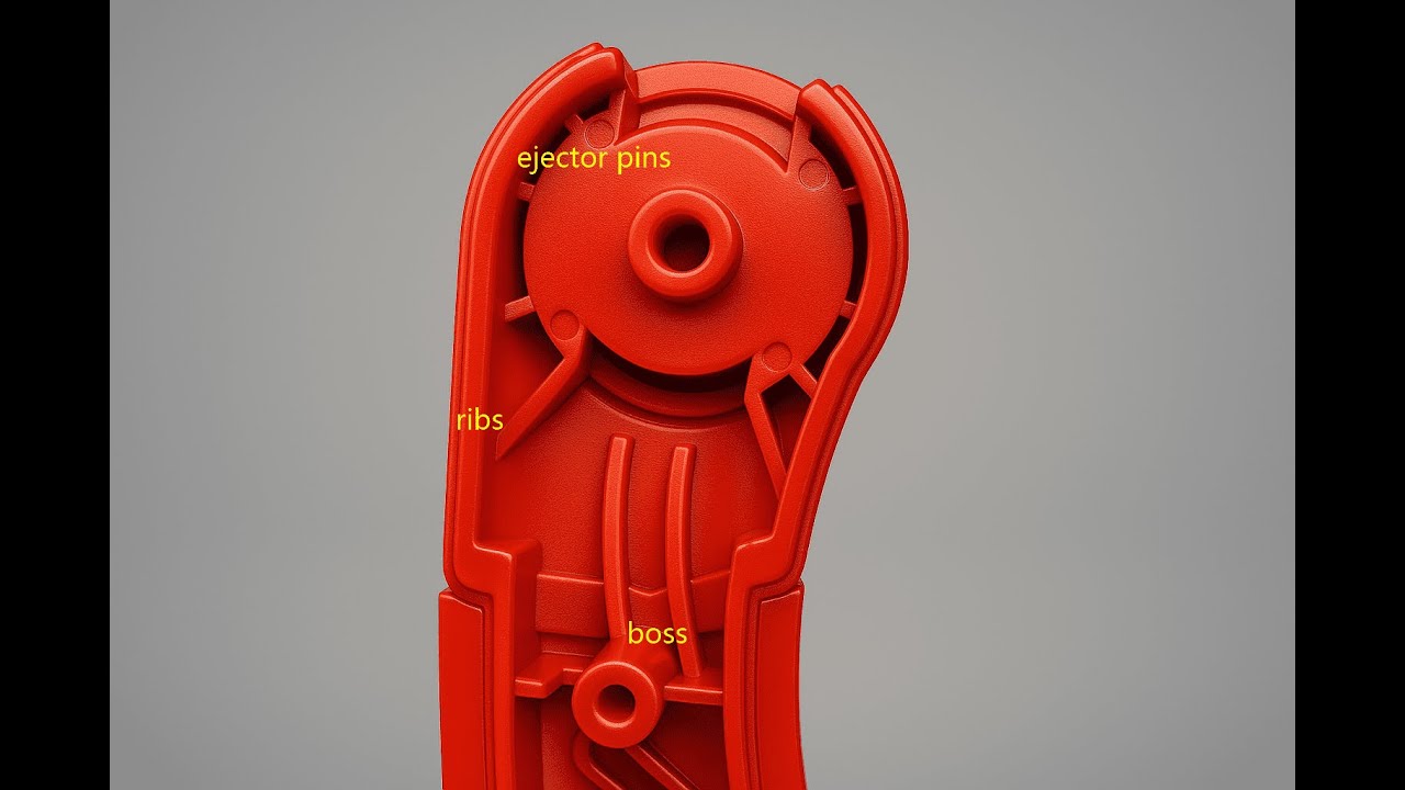
- Es malo tener fregaderos (densidades en las superficies causadas por secciones más gruesas de plástico que se ralentizan al enfriarse). Es importante seguir estas directrices para minimizar o eliminar la aparición de manchas en las superficies cosméticas:
- Asegúrese de que las superficies estéticas importantes no tengan rejillas, nervaduras, salientes de tornillos, etc. en la parte posterior;
- Rib height should not exceed three times the wall thickness;
- Rib base thickness should be 50–60% of the connecting wall thickness.
- Los territorios se definen por datums. Para establecer la interfaz y la interacción entre las piezas, se utilizan puntos de referencia (características que sirven como puntos de referencia para las piezas). Cuando una intención de diseño coincide con una estructura de puntos de referencia, un producto puede funcionar correctamente.
- Los interrogatorios no tienen nada de malo. En DFM (diseño para fabricación), el moldeador comunica su comprensión del diseño, especialmente en lo que respecta a la ubicación de los pasadores, la ubicación de las compuertas y las líneas de separación (que podrían afectar a la forma en que interactúan las piezas). Interrogar el diseño mediante informes de inspección.
- Crear prototipos a menudo y en una fase temprana. Las técnicas actuales de creación de prototipos, incluida la impresión en 3D, pueden reducir los costes de material al permitir modelar componentes y/o la pieza completa antes de construir costosas herramientas.
Directrices de diseño de moldeo por inyección
Essential rules for strong, manufacturable plastic parts. All values reference nominal wall thickness T, hole diameter D, or hole width W.
Geometry
Espesor de pared
Inconsistent thickness causes warping and sink marks.
Corner Radii
Reduces stress concentration and improves plastic flow.
Ángulos de calado
Costillas
Agujeros
Add bosses and connecting ribs for reinforcement.
Proceso
Selección de materiales
Choice drives required wall thickness and draft angles.
Ejection & Parting
Simplifies mold design and reduces post-processing.
Los 6 tipos de moldeo de plástico
Plastic molding includes several manufacturing processes used to shape plastic materials into finished products. Each molding method is suitable for different product structures, production volumes, materials, and cost requirements.
Comparison Table: 6 Common Plastic Molding Methods
| Plastic Molding Type | How It Works | Best For | Key Advantages |
|---|---|---|---|
| Moldeo por inyección | Molten plastic is injected into a mold cavity, then cooled and solidified. | High-volume plastic parts, precision components, housings, connectors | Fast production, high accuracy, consistent quality |
| Moldeo por soplado | Heated plastic is inflated with air inside a mold to form a hollow shape. | Bottles, containers, tanks, hollow packaging | Ideal for hollow parts, lightweight products, thin walls |
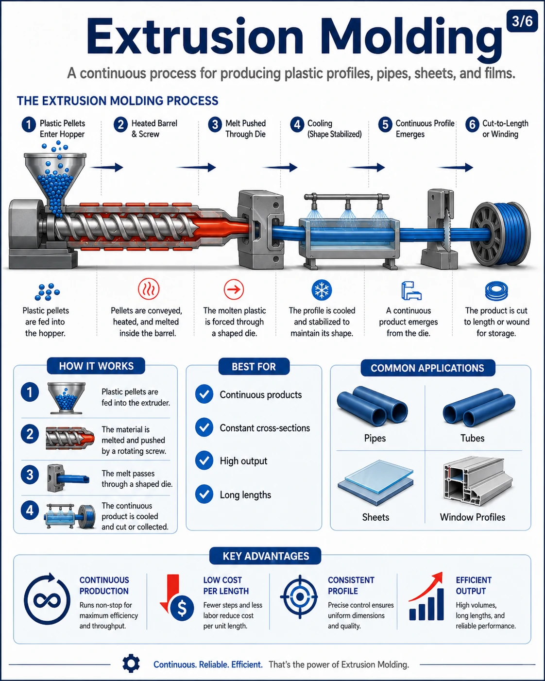
| Extrusion Molding | Melted plastic is pushed through a die to create a continuous profile. | Pipes, tubes, sheets, profiles, films | Continuous production, low cost per length, stable cross-section |
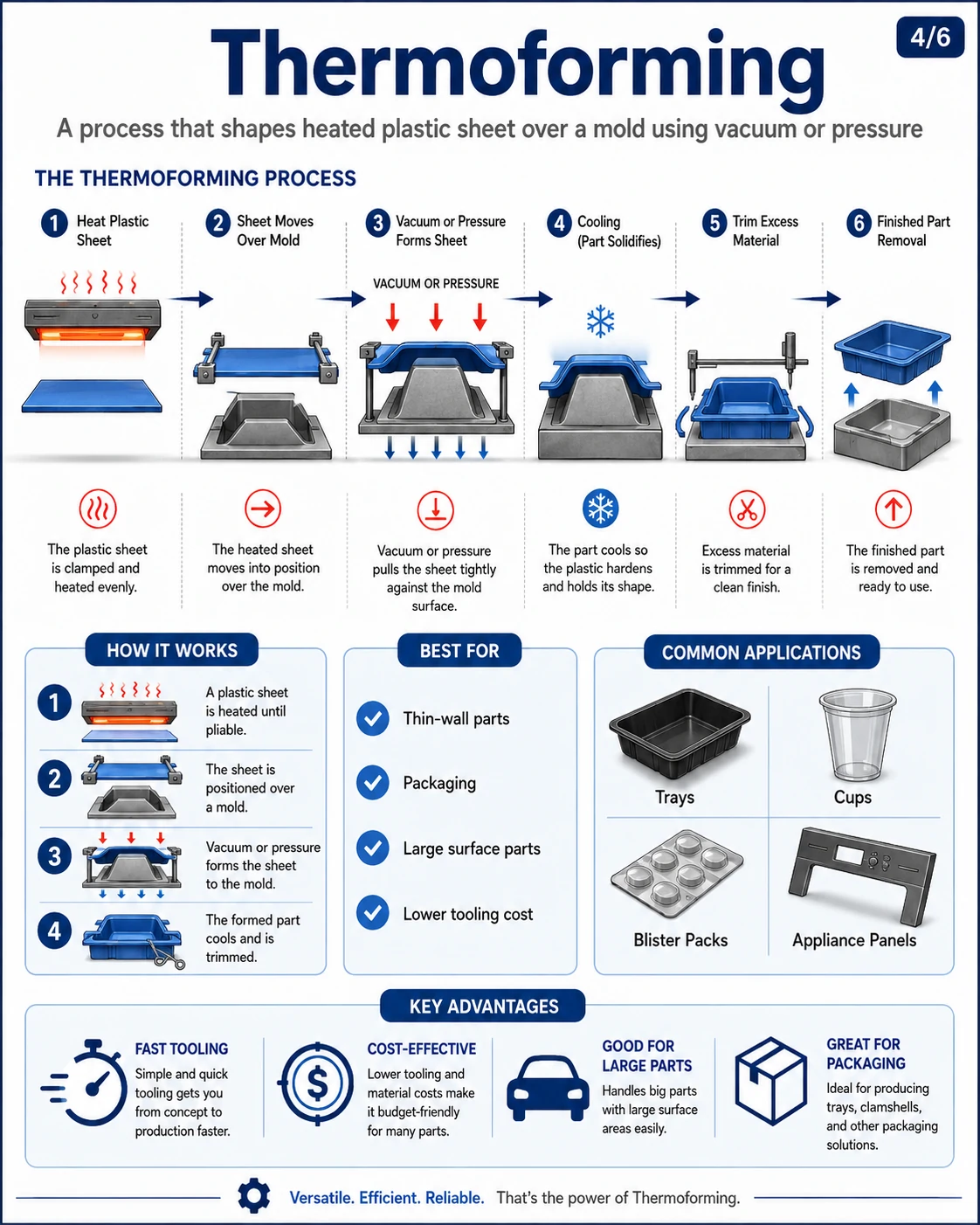
| Thermoforming | A heated plastic sheet is formed over a mold using vacuum or pressure. | Trays, cups, packaging, panels, covers | Low tooling cost, fast prototyping, suitable for large thin parts |
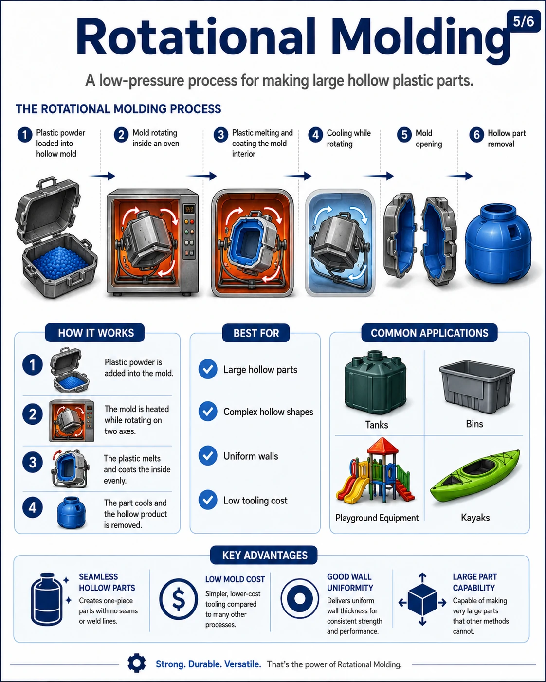
| Moldeo rotacional | Plastic powder is placed in a mold and rotated while heated until it coats the mold interior. | Large hollow parts, tanks, bins, playground equipment | Good for large hollow products, low tooling cost, uniform wall thickness |
| Compression Molding | Heated plastic material is placed into a mold and pressed under high pressure. | Rubber-like parts, thermoset parts, electrical components, simple shapes | Strong parts, suitable for thermosets, lower material waste |

Pros and Cons of Plastic Injection Molding
| Category | Pros (Advantages) | Cons (Disadvantages) |
|---|---|---|
| Accuracy | High precision and repeatability. Capable of producing complex and detailed geometries. | High precision also means errors in design can lead to costly defects. |
| Velocidad de producción | Very fast cycle time (about 15–20 seconds). Ideal for high-volume mass production. | Initial setup and mold design can take weeks or months. |
| Eficiencia de costes | Low cost per unit in large-scale production. Automation reduces labor costs. | High upfront costs for molds, machines, and tooling. |
| Labor Requirements | Mostly automated; fewer operators needed once production starts. | Requires skilled technicians for mold design, setup, and quality control. |
| Versatilidad | Suitable for a wide range of products, from small electronic parts to large automotive components. | Limited by machine size and material constraints. |
| Sostenibilidad | Minimal material waste during production. Some plastics can be recycled and reused. | Difficult to recycle complex or multi-material molded parts. |
| Product Quality | Consistent quality across large production runs. | Possible defects such as warping, sink marks, or flash if process is not optimized. |
| Scalability | Excellent for large-scale and continuous manufacturing. | Not cost-effective for small batch or low-volume production. |
