To understand the various designs of undercut mould, we must first understand the definition of what a moulded undercut really is.
In its most simplistic form, an undercut can be described as any feature on the moulding which resists the line of the draw or inhibits the ejection of the moulding from the mould.
To avoid undercut of parts, the design of the part should be changed to avoid undercuts if possible. Ideally, mould tools ought to open in a direction corresponding to the injection moulding machine’s movement.
It is possible to strip slight undercuts from the tool following component shape. If the component’s edges are tapered in such a way as to prevent scuffing, this could be acceptable.
Moulded features which include retention beads,grooves,side holes, deeply eroded surface finishes, reverse draft angles, internal and external rigid threads can all be classified as undercut features if they resist the line of draw.
In many situations, it is possible to create the desired geometry without having to be restricted to using mechanical devices.
For some complex components, it is necessary to use side cores, mechanically operated cams or loose cores.
To eject such features from the mould, the forming parts of the mould must be retracted before ejection taking place. This pre-ejection removal of the mould coring components is usually referred to as core pulling.
Core pulling
Core pulling is an expensive business and should only be undertaken when no alternative option exists. The need to core-pull a feature has to be identified at a very early stage before the mould build-up has been started.
To enable a cored feature to be pulled out of the line of draw, sufficient space within the mould bolster must exist in which the pulling mechanism can be actuated and housed.
The amount of movement required to clear the undercut feature, e.g. length of the screw thread to be unwound or the length of the side core pins to be retracted,plus clearance, has to be predetermined.
Additionally, the design of the pulling actuation system should also be considered and its movement requirements allowed for when deciding upon the size of the bolster.
To do this, the mould designer must know about the various designs of actuation systems available and make a choice of which one is best suited to the required application.
Core pulling actuation methods
Cam pin actuation
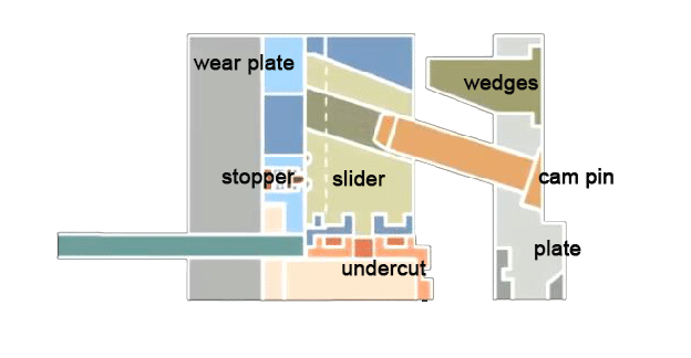
Cam pin actuation is one of the most commonly encountered core pulling methods, being easy to install and relatively cheap to obtain as a set of standard mould components. The cam pin assembly (Figure 12.2) consists of four basic component parts:
- the moving insert block;
- the block retention slides;
- the heal block;
- the cam pin.
When fitted to the mould,the cam pin and heal block components are usually situated in the cavity half of the tool. The insert block and slide assembly are installed in the core half of the tool facing the cam pin and heal block assembly.
On the closure of the mould,the angled cam pin locates into the correspondingly angled hole in the sliding insert block. As the mould proceeds to close, the cam pin slides into the angled insert hole forcing the block to move toward the core shut-off.
The cam and block assembly is set in such a manner as to enable the side core pin to fully contact the mould core shut-off, without excessive contact force being transmitted. The amount of moving insert block movement is governed by the engagement angle of the cam pin assembly.
Angles vary from as low as 10° to as high as 45° to the vertical,dependent on the amount of side movement required. To minimise cam pin and block wear, cam pins should be kept short and the engagement angle should be as shallow as possible.
Cam action assemblies are also susceptible to damage if the wrong mould closing sequence is used, i.e. the cam pin is misaligned with the insert block hole before the closure of the mould. To minimise the risk of misaligning the cam pin assembly,the following preemptive measures can be taken:
- (a) Preload the moving insert block to ensure the block is held in the fully open position with the mould open. This is achieved by attaching a spring to the block which is loaded when the mould is partially or fully closed.
- (b) Arrest block movement in the open position with the aid of spring-loaded ball catches located underneath the moving block. The ball catch loading is only sufficient to suppress the minor movement of the block encountered during normal processing conditions. The inclusion of ball catches also serves to reduce wear generated by minor misalignment of the cam pin assembly when in use.
- (c) Use a ‘mould safety, micro-switches circuit ,actuated by the positional location of the moving insert block. The movement of the moving insert block serves to open and close the circuit micro-switch. With the block in the fully open position the switch is depressed, the circuit is said to be, made, and the mould may close without damage resulting. If the block is not in the fully open position and the micro-switch is undepressed or not made\ an open circuit exists. Since the mould safety circuit is linked in series to the recycle switching circuit of the moulding machine, the machine will not receive a recycle signal and will stop with the platens in the open position. The machine will then sound the alarm signal to inform the operator that something is amiss. The insert block can be accordingly reset to allow production to continue.
Lost action cam pins
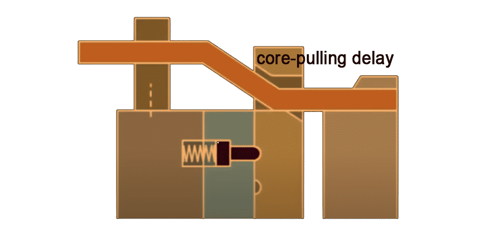
These are often referred to as ‘dog leg’ cams due to their appearance. Lost action cams are employed when a core-pulling delay is required during the mould opening phase.
In this case, the parallel part of the pin enables the mould to move apart without initially moving the side core blocks.
Movement of the side core components only starts when the mould has opened sufficiently enough to engage the angled section of the cam pin within the side core block hole.
Once engaged, the cam pin actuates the block movement like any normal cam pin pulling sequence. Lost action cam pin assemblies are typically employed when moulded undercut features are required to retain the moulding on a desired half of the mould, usually for ejection purposes.
The increased length of the dog-legged pins, compared to conventionally straight cam pins, means they are more easily damaged if abused in use.
Additionally, deeper mould bolsters have to be employed to house the extra pin lengths resulting in reduced working daylight once set in the moulding machine.
Action wedges
The wedge actuation technique is frequently used when there is a need for minimal side core movement with which to clear the moulding. Moulded features which include textured surface finishes,reverse draft tapers and shallow coring features may be produced using this pulling actuation method. The wedge assembly comprises four basic components:
- (i) the action wedges;
- (ii) the side core block;
- (iii) the block slides;
- (iv) the return wedge.
The actuation force is applied to the tapered underside of the side core block by the action wedges, forcing the block away from the mould centre core. The action wedges,being retained in the mould ejector plate assembly, are essentially part of the ejection system.
To enable the side core blocks to move before the ejection of the moulding,the action wedges tend to be longer than their accompanying ejector pins. Following mould opening, wedge actuation and component ejection, the side core blocks are returned to shut-off against the mould centre core. This is achieved by the pushing action of the return wedge against the tapered back of the side core block as the mould closes. Retraction of the mould ejection system must happen before mould closure if the damage is to be avoided to the underside of the side core blocks and the action wedges.
The incorporation of a mould safety circuit actuated by the return of the ejector plate assembly would ensure action wedge removal before mould closure. The principle of wedge action core pulling, although simple in theory,requires a good standard of toolmaking to achieve the moulding shut-off requirements demanded by the tool build-up. Some of the most commonly encountered problems associated with wedge action tools are listed and explained below:
- (a) Grease contamination – leakage of grease from the side core block slides working its way into the moulding area and contaminating the moulding. Keeping grease levels to a minimum within the slide area reduces the risk of contamination. This is achieved by regular removal and cleaning of the side action blocks when in use. In cases of minor contamination of lightly coloured mouldings, the use of white silicone-based grease may prove beneficial.
- (b) Wedge and slide wear – wearing of the return wedge and the block slide faces will eventually result in a poor core shut-off and flash occurring. The addition of hardened steel wear pads, containing grease grooves,into the wear faces enable tool wear to be compensated for (by packing behind the pad),with the ability to re-machine the contact faces.
- (c) Mould seizure – seizure generally occurs in wedge action tools between the opening action wedges and the side core blocks themselves. Lack of grease causes frictional overheating to occur. This dries out the remaining lubricant resulting in scuffing and seizure of the moving parts. The addition of grease grooves to the sides of the action pins will reduce this problem. However, in some cases, the choice of steel type and hardness has a bearing on the wear resistance of the moving parts.
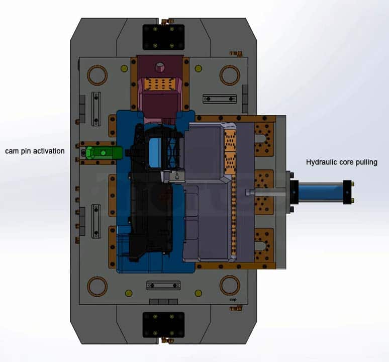
Hydraulic core pulling
Most modern moulding machines are hydraulically powered but not all machines are fitted with auxiliary hydraulic circuits. In cases where spare auxiliary circuits are available, the mould can utilise them for core pulling purposes.
The figure below illustrates a simple hydraulically actuated pulling system,in which pressurized hydraulic oil is used to move the cylinder piston. Forward movement of the piston pushes the linked side core block inward against the centre core shut-off.
Outward movement of the core block is achieved by diverting the pressurized oil flow from the top of the piston crown to the crown underside. This is usually achieved by employing a servo valve actuated by the machine control system.
While the side cores are in contact with the centre core during the filling and cooling stages of the moulding cycle, an oil pressure loading is maintained. Sufficient pressure should be applied to avoid the side cores being forced back by the increasing injection force as the impression fills.
As a result of the auxiliary nature of this actuation method, mould safety must be adequately catered for if the damage is to be avoided. Most damage is usually inflicted by the inward actuation of the pulling circuit with the mould open.
Subsequent closure of the mould often results in core breakage or shut-off damage. Mould safety circuits on hydraulically actuated moulds should not rely on a single micro-switch actuated in the core back position.
In such cases, two switches should be employed: one at the side core block front position, the other in the conventional rear position. A system used in this manner is usually referred to as a tandem safety circuit. The signals generated are used to control the opening and closing of the moulding machine.
The principal advantages of using hydraulics as a core-pulling actuation method are:
- (a) Loading forces can be easily controlled and adjusted while in use;
- (b) High closure and holding loads can be generated and maintained.
The principal disadvantages of hydraulic actuation include:
- (a) Movement damping (deceleration of movement) can prove to be difficult to achieve at higher loading pressures;
- (b) Hydraulic systems tend to be messy and are prone to contaminate their working locality.
Pneumatic core pulling
The use of pneumatics (pressurised air) instead of hydraulics represents a cheaper alternative but is fraught with problems. The industrial line pressure in most modern factories is approximately 80 psi. Compressed air above 80 psi is more expensive to produce and is therefore rarely encountered.
This fact serves to highlight the main problem associated with pneumatic pulling actuation: low holding force. In many cases, a pneumatically held side core would simply be forced back by the first stage injection pressure.
However, for small mouldings or processing involving lower injection pressures, e.g. some examples of foam moulding, pneumatic actuation and core holding may be utilised.
The design layout of a pneumatic actuation system is very similar to that of the hydraulic system but consists of pneumatic cylinders and components. Pneumatic components are available from a wide range of suppliers and can be replaced as standard mould parts as and when required. The same mould safety considerations are equally relevant with pneumatic actuation as they are with hydraulic actuation.
The principal advantages of employing pneumatic as a core-pulling actuation method are:
- (a) Speed of actuation and movement – pneumatically actuated components are fast and efficient,enabling fast-cycling if required.
- (b) Cleanliness – when supplied with filtered or ‘scrubbed’ air, pneumatics may be used for ‘clean room’ environment applications,e.g. medical moulding and robotics.
- (c) Cheapness – pneumatic components are relatively cheap to obtain and maintain while in use.
The principal disadvantages of employing pneumatics as a core-pulling actuation method are:
- (a) Low holding force once applied.
- (b) Noise – due primarily to the exhausting of actuation cylinders when in use. Pneumatic noise tends to be high pitched and is therefore frequently over the safe working threshold limit for unprotected hearing.
- (c) Moisture – condensation may appear within the factory compressed air supply and is most pronounced if the compressor is sited outside the factory main building. The installation and use of condensation traps along supply lines help to reduce the moisture problem. Condensation may also appear within pneumatic cylinders buried within mould plates, especially in cases where chilled water is being used to cool the mould. Corrosion and piston sticking may result if pneumatic piston chambers and pipes arc not cleared after mould use.
- (d) Pressure fluctuation 一 pneumatic line pressure is invariably subject to fluctuation during the course of a typical factory working day as a result of changing demand. Pressure drops tend to slow actuation speeds and reduce holding pressures whereas pressure increases result in the opposite effect.
Electromechanical core pulling
Electric motors are frequently employed to actuate and power core un-screwing mechanisms. In most cases, power from the motor is transmitted via a gear drive system to the subject core(s) to be rotated.
Component unscrewing is generally achieved with the mould in the closed position. This is to ensure that the moulding does not move or rotate while the thread is being disengaged.
To enable rotation, the core body is supported on bearings on either side of the keyed drive gear. The core body, being freely supported,is allowed to travel back into the mould as the core thread is unwound from the moulding. Once unwound, the electric motor is deactivated by a micro-switch positioned behind the moving core.
The mould is then opened and the moulding ejected conventionally. After ejection, the mould is closed and the cores moved forward for the next shot. The process is repeated.
Apart from the electro-mechanical unscrewing method previously mentioned, many other unscrewing techniques are commercially employed.
One of the most commonly employed non-electric unscrewing devices is based on a ‘fast’ helix screw thread actuated by the opening act of the mould.
Such mechanisms can be obtained from catalogue order mould part suppliers and fitted as standard mould components. Whichever unscrewing device or mechanism is employed, attention should be given to providing an adequate mould safety system to adequately protect the tool when in use.
Also, we could find some other solutions for undercut:
-
Deflect:
It is possible to handle small undercuts easily by bending the part out of the mould.
-
Inserts:
It may be possible to manufacture some undercuts with the use of removable inserts that are ejected with the part.
The method for replacing inserts in the mould for the next cycle and removing them from the ejected part will require a particular method of manufacturing that is unique.
-
Stepped parting line:
Sometimes the parting line can be moved to become a straight surface so that no undercut occurs. This can make the mould design progressively more complex, but it is always recommended to achieve a straight surface.